
Specifications
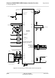
Table Of Contents

Cinterion
®
EHS5-E/EHS5-USR4 Hardware Interface Overview
3.2 Power Supply
30
ehs5_hio_v04.000 2019-01-16
Confidential / Preliminary
Page 30 of 46
3.2 Power Supply
EHS5-E/EHS5-USR4 needs to be connected to a power supply at the SMT application inter-
face - 2 lines BATT+, and GND. There are two separate voltage domains for BATT+:
•BATT+
BB
with a line mainly for the baseband power supply.
•BATT+
RF
with a line for the GSM power amplifier supply.
Please note that throughout the document BATT+ refers to both voltage domains and power
supply lines - BATT+
BB
and BATT+
RF
.
The power supply of EHS5-E/EHS5-USR4 has to be a single voltage source at BATT+
BB
and
BATT+
RF
. It must be able to provide the peak current during the uplink transmission.
All the key functions for supplying power to the device are handled by the power management
section of the analog controller. This IC provides the following features:
• Stabilizes the supply voltages for the baseband using low drop linear voltage regulators and
a DC-DC step down switching regulator.
• Switches the module's power voltages for the power-up and -down procedures.
• SIM switch to provide SIM power supply.