
Specifications
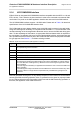
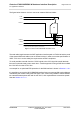
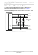
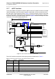
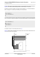
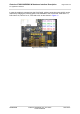
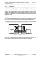
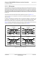
Table Of Contents
- Contents
- Tables
- Figures
- 1 Introduction
- 2 Interface Characteristics
- 2.1 Application Interface
- 2.2 RF Antenna Interface
- 2.3 GNSS Interface
- 2.4 Sample Application
- 3 Operating Characteristics
- 3.1 Operating Modes
- 3.2 Power Up/Power Down Scenarios
- 3.3 Power Saving
- 3.4 Power Supply
- 3.5 Operating Temperatures
- 3.6 Electrostatic Discharge
- 3.7 Blocking against RF on Interface Lines
- 3.8 Reliability Characteristics
- 4 Mechanical Dimensions, Mounting and Packaging
- 5 Regulatory and Type Approval Information
- 6 Document Information
- 7 Appendix

Cinterion
®
EXS62-W/EXS82-W Hardware Interface Description
2.1 Application Interface
61
t EXS62-W_EXS82-W_HID_v01.200ee 2022-09-07
Public/ Released
Page 34 of 144
2.1.7 eUICC Interface
As an option EXSx2-W supports an eUICC in MFF-XS format. This MFF-XS eUICC is located
under the shielding, is only connected to specific module pads, and has no physical connec-
tions with other circuits inside the module. Figure 13 shows an example of how to connect the
eUICC to the module’s SIM interface lines as well as a switch to select whether to use the in-
ternal MFF-XS eUICC or an external plug-in SIM card. Figure 14 shows an example for a direct
connection to the module’s SIM interface lines
Figure 13: eUICC interface with switch for external SIM
The eUICC interface comprises five lines (plus ground) as listed below in Table 5.
Table 5: Signals of the eUICC interface option (SMT application interface)
Signal Pad no. Description
CC2_RST 249 Chip Card Reset
CC2_CLK 247 Chip Card Clock
CC2_IO 248 Chip Card I/O (data line)
CC2_VPP 106 --
CC2_VCC 246 Operating Voltage for SIM card (=1.8V)
GND -- eUICC Ground
Module
Max. distance 10cm
SIM card holder
SIM
eUICC
CCIO pull up resistor and
VSIM capacitor 2.2µF
are mounted on the module
CC2_VCC capacitor 2.2µF mounted on the module
VSIM
CCIO
CCRST
CCCLK
CC2_VPP
CC2_VCC
CC2_IO
CC2_RST
CC2_CLK
SIM_SWITCH to
drive SIMSELECT
Common
If 1
If 2
SIM
switch
FSA2567
SIMSELECT
Alternatively SIM switch can be bridged
44
4 x 0R
ESD
protection
SIM inserted =>
Switch closed
SIM_SWITCH = Low => SIMSELECT = High: SIM connected
SIM_SWITCH = High => SIMSELECT = Low: eUICC connected
VBATT
10k
22k
100k
CCIN
100k
100k
V180
100k
100p
10k
C C IN ( “Ap plica tion “):
low = > card inserted
high => card removed
CC IN (“Module “):
high = > card inserted
low => card rem oved
See 2.1.6.1