LINK 740 Installation Guide 1586894820069 - Draft - 2020-06-05
Contents Installation...................................................................................................................................... 4 Read me first......................................................................................................................................... 5 Congratulations................................................................................................................................5 What’s in the box.......................................
Responsible party in Chile..............................................................................................................39 Responsible party in Mexico.......................................................................................................... 39 Emmisions information for Canada................................................................................................ 39 Mexico..................................................................................................
Installation 4
Read me first Congratulations You have chosen the LINK 740, a core hardware component from WEBFLEET. With WEBFLEET you are always connected to your vehicles out on the road in a smart and easy way. LINK 740 is a GNSS receiver and mobile network module in one unit, always providing the vehicle’s current position. When used with a compatible Driver Terminal, you can easily handle orders, as well as text and status messages.
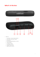
What’s in the box • LINK 740 1. 2. 3. 4. 5. 6. 7. 8. 9. Yellow LED - connection status indicator. Green LED - system status indicator. Reset button. Service/Update Mini-USB-cable connector. 1-Wire-Interface. I/O-cable connector. Power/CAN connector. CAN DIP switch (sealed). GNSS antenna connector.
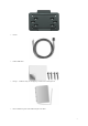
• Holder • Power/CAN cable • Fixings - 1 adhesive strip, 4 self-tapping screws and a cleaning tissue • Basic installation guide and additional QR code labels 7
What you need for the installation Before starting the installation of your LINK 740, read the installation instructions and the safety notices and warnings carefully and make sure you have the following: • The Contract Confirmation letter including the Activation Code. • A device with internet connection that is able to scan QR codes, has the LINK Toolkit app installed and the necessary LINK Tookit login credentials. • The QR code of the LINK 740 (on the device label or on the additional QR code label).
Safety first Important safety notices and warnings Important: Read the following safety instructions carefully. Read the instructions in this document carefully. Webfleet Solutions accept no liability for damage that results from disregarding the safety instructions. This document is part of the product. Keep it in a safe place. If you pass the unit on to a new user, make sure you give them this document as well.
Damage to the device Short-circuits inside the unit can be caused by contact with water or other liquids. The unit may be damaged by contact with water. Use and store the unit in an area protected from water.
Connection overview Connection overview: Power/CAN cable * Make sure this wire is fused with max. 10A. ** Twisted pair. Loose ends of CAN L/CAN H wires must be protected against short circuits. Separate by using a heat shrink tube. *** Only one of the CAN2 ports can be used.
Connection overview: 12 PIN IO cable ** Twisted pair. Loose ends of CAN L/CAN H wires must be protected against short circuits. Separate by using a heat shrink tube.
Connecting to the CAN bus Please refer to the Webfleet Solutions tooling for the CAN configuration of your specific vehicle. Important! If you need to alter the setting of the CAN DIP switch, re-cover the switches using the red seal, taking care to close the rubber cover completely. Tips for the installation • • • • • For direct connection to the CAN bus select the wire to be as short as possible and needed. Do not wind the CAN wires.
Connecting to power Note: If want to connect the LINK CAN Sensor 100 to your LINK 740, please use the Data/Power Cable supplied with the LINK CAN Sensor 100. Connect the LINK 740 to the vehicle power supply with the standard vehicle voltage (12 V/24 V). Do not connect to a voltage converter. The three wires GND, IGN and PWR+ (supply voltage) must be connected. Important: Follow the order of connecting the wires as described below. First connect the wires then insert the plug into the LINK 740.
Choosing the correct position First you need to choose the correct position in which to install your LINK 740. Take the following into consideration: • • • Do not expose the LINK 740 to direct sunlight and/or high temperature for long periods to ensure proper operation. For optimal GNSS reception using the integrated GNSS receiver, the top of the device must not be obstructed by metal items.
Mounting the LINK 740 Your LINK 740 comes with an integrated mobile network antenna and an integrated GNSS antenna. Depending on the position you choose for the installation, you can install your LINK 740 without an external GNSS antenna. The LINK 740 can be attached with the two adhesive strips or the two tapping screws. You can attach the holder to the top or to the bottom side of the LINK 740.
Important: Use the strip only in combination with the holder. Do NOT place the strip on the serial number sticker of the device. 5. Remove the protective film from the other side of the strip. 6. Place the holder with the adhesive strip on the prepared surface. Press it gently for a few seconds until it sticks. Note: The full strength of the strip will be reached after approximately 72 hours depending on the temperature. 7. Insert the LINK 740 into the holder. Press gently until it clicks into place.
Mounting the external GNSS antenna If you install the LINK 740 in a position where it has poor GNSS reception, you need to use the external GNSS antenna accessory from Webfleet Solutions, which comes with an integrated magnet and an adhesive pad. The external GNSS antenna from Webfleet Solutions is not part of the standard LINK 740 product package. Important Only use the GNSS antenna from Webfleet Solutions, otherwise GNSS performance may be poor or not work at all.
3. Prepare a smooth, clean, oil free and dry surface on the windscreen. 4. Attach the antenna to the prepared surface so that the top side has a clear view of the sky. Either locate a smooth metal surface or use the extra adhesive pad.
Testing operation Testing operation with the LINK Toolkit app In addition to the tests described below you can also test the operation of your LINK 740 using the LINK Toolkit app. Power or Ignition test Before testing the connection to power and to the ignition make sure you have properly carried out the installation. 1. Check all connections to your LINK 740 device (wires, fuses etc.). 2. Turn off the ignition. The green LED should be off and then go on every 3 seconds. 3. Turn on the ignition.
Activating the LINK 740 You can use the LINK Toolkit app which will guide you through the activation process of your LINK 740 device. Make sure you have the following: • The Contract Confirmation letter including the Activation Code. • A device with internet connection that is able to scan QR codes, has the LINK Toolkit app installed and the necessary LINK Tookit login credentials. • The QR code of the LINK 740that you can find on the device label or on the addtional QR code label.
Diagnostics Monitoring operation You can monitor the system operation of your LINK 740 by looking at the green system LED and referring to the table below. Important: The LINK 740 device must be activated in WEBFLEET. GREEN LED mode OFF Unit is in standby mode or is not connected to power. • Switch on ignition. • Check if the device is properly connected to power. OFF and short ON every 3sec Ignition off. Flashing No operating system and/or no application available or application failed.
ON and short OFF every 3sec Connecting. • If for longer than ten minutes, please contact the Webfleet Solutions support team at www.webfleet.com/ support. ON Connected. Support If you cannot find the answer to your question with the help of the tables above, please contact the Webfleet Solutions support team at www.webfleet.com/support.
Resetting the LINK 740 If your LINK 740 does not operate properly or signals a system error you may need to restart or reset the unit. Only restart or reset the LINK 740 after you have made sure you have carried out all previously described steps without success. Restarting your LINK 740 To restart your LINK 740, press the reset button with a thin pointed object until it clicks and keep it pressed down for 1 to 2 seconds. The LINK 740 restarts within approximately five seconds after releasing the button.
Technical data Dimensions Body: 122 x 59 x 24 mm / 4.8 x 2.23 x 0.94 inches Body with Holder: 122 x 63 x 28.3 mm / 4.8 x 2.48 x 1.11 inches Weight Body: 110 g / 3.88 ounces Holder: 14 g / 0.49 ounces Material Body and holder: Injection moulded plastic PC/ABS Protection class IP 20 Supply voltage 12 V / 24 V (min. 9 V to max. 30 V) Current / power conAt 14 V: typically < 0.05 A / < 0.7 W sumption (average values)At 28 V: typically < 0.03 A / < 0.84 W Standby: typically < 0.0015 A / < 0.
GNSS antenna connector SMB (male) - (antenna - female) for external GNSS anten- Supply voltage range 3.3 V na Minimum antenna gain at 3 V: 20 dB (optional accessory) Maximum antenna gain: 40 dB Maximum noise rating: 1.5 dB Bluetooth® Integrated Bluetooth® (class 2) for connection to Driver Terminals and accessories. 1-Wire Interface A 4-pin MicroFit connector with 1-wire interface and LED current source (approx. 17 mA) for an indicator light is available. The 1-Wire master is using a 3.3 V supply.
LEDs Green LED indicates the system status Yellow LED indicates the connection status Primary battery 3 V non-rechargeable, this device cannot be operated with this battery 27
Appendix: Using the I/O connector Using the 12 pin I/O cable, you can connect to a digital tachograph, as well as use configurable digital inputs and outputs to connect accessories and 3rd-party devices. For example, you can record inputs, for keeping a digital logbook with the help of a switch, reporting times the vehicle is idling etc. You can connect the 12 pin I/O cable from Webfleet Solutions to the 12 pin I/O cable connector of the LINK 740. ** Twisted pair.
change-over switch, switching the digital input between plus and minus (ground GND) of the vehicle electrical system voltage (+9 ... 30 V). If no change-over switch is available, an electric load for example, indicator light or resistor, between the digital input and ground (GND) or between the digital input and the vehicle voltage (+9 ... 30 V) can offer defined levels. When using inductive loads, a free-wheeling diode must be used in parallel with the load.
Wiring the digital output The digital output OUT of the LINK 740 is an open drain output linking to ground. The connected load must be connected between vehicle voltage and OUT. Loads requiring more than 0.35 A must be controlled with relays. If the load requires more than the maximum output voltage use a 12 V/24 V relay, depending on the operating voltage. Caution: Do not switch safety relevant vehicle functions.
Using the IN and OUT for changing the logbook mode You can change the logbook mode using the IN/OUT of your LINK 740. Connect a normally open momentary push button switch and an indicator light to the IN/OUT. This requires configuration in WEBFLEET. You can use a normally open momentary push button switch and a separate indicator light or a switch with an integrated indicator light. Connect a normally open momentary push button switch and indicator light to the IN/OUT.
Addendum 32
Important Safety Notices and Warnings Global Positioning System (GPS) and Global Navigation Satellite System (GLONASS) The Global Positioning System (GPS) and Global Navigation Satellite System (GLONASS) systems are satellite-based systems that provide location and timing information around the globe. GPS is operated and controlled by the Government of the United States of America, which is solely responsible for its availability and accuracy.
Other medical devices Please consult your physician or the manufacturer of the medical device, to determine if the operation of your wireless product may interfere with the medical device. Device care • • It is important to take care of your device: Do not open the casing of your device under any circumstances. Doing so may be dangerous and will invalidate the warranty.
Operation is subject to the following two conditions: (1) this device may not cause harmful interference and (2) this device must accept any interference, including interference that may cause undesired operation of the device. This device has been tested and found to comply with the limits for a Class B digital device, pursuant to part 15 of the FCC rules. These limits are designed to provide reasonable protection against harmful interference in a residential installation.
Specific Absorption Rate (SAR) compliance THIS WIRELESS DEVICE MODEL MEETS GOVERNMENT REQUIREMENTS FOR EXPOSURE TO RADIO WAVES WHEN USED AS DIRECTED IN THIS SECTION This device is a radio transmitter and receiver. It is designed and manufactured not to exceed the emission limits for exposure to radio frequency (RF) energy set by the Council of the European Union, Innovation Science and Economic Development Canada (ISED) and the Federal Communications Commission of the U.S. Government.
User replaceable batteries must only be used in systems for which they are specified. Caution: Risk of explosion if the battery is replaced by an incorrect type. Do not remove or attempt to remove the non-user-replaceable battery and contact a qualified professional in case you wish to remove it. Failure to follow these guidelines may cause the battery to leak acid, become hot, explode or ignite and cause injury and/or damage. Do not attempt to pierce, open or disassemble the battery.
WEBFLEET If your vehicle is configured to connect to WEBFLEET services, it will collect information for the purposes of the WEBFLEET service while the vehicle is in use in association with other WEBFLEET equipment installed in the vehicle. The following information is continuously collected: vehicle location, g-force/acceleration data, and engine-related data such as fuel consumption, valve positions, engine speed, and odometer value.
Model numbers LINK 740: L0740 GNSS system Model: LINK 740 Brand: Webfleet Solutions PRODUCED IN CHINA Responsible party in North America TT Telematics USA Inc., 100 Summit Drive, Burlington, MA Responsible party in Chile Webfleet Solutions Chile SpA , Apoquindo 3910, Piso 8, Edificio Las Torcazas, Las Condes, 7550029 Santiago, Chile Responsible party in Mexico Webfleet Solutions Mexico S.A de C.V., Torre Diana, Calle Río Lerma 232, Cuauhtémoc, 06500 Ciudad de México, CDMX.
Chile This product has been verified by SUBSECRETARÍA DE TELECOMUNICACIONES with homologation number n.a. Warning for Australia The user needs to switch off the device when exposed to areas with potentially explosive atmospheres such as petrol stations, chemical storage depots and blasting operations. Notice for New Zealand This product displays R-NZ to show it complies with relevant New Zealand regulations.
New Zealand: 09915 0241 This document Great care was taken in preparing this document. Constant product development may mean that some information is not entirely up to date. The information is subject to change without notice. Webfleet Solutions shall not be liable for technical or editorial errors or omissions contained herein, nor for incidental or consequential damages resulting from the performance or use of this document.
The Bluetooth® word mark and logos are registered trademarks owned by Bluetooth SIG, Inc. and any use of such marks by Webfleet Solutions is under licence. Other trademarks and trade names are those of their respective owners. OpenSynergy OpenSynergy This product uses Blue SDK from OpenSynergy GmbH. The following copyright notice applies for BlueSDK: © OpenSynergy GmbH – All right reserved Blue SDK SHA1, SHA2, HMAC and Key Derivation in C, Brian Gladman Copyright (c) 2003, Dr Brian Gladman, Worcester, UK.
AND NON-INFRINGEMENT. THIS SOFTWARE IS PROVIDED ON AN "AS IS" BASIS, AND THE AUTHORS AND DISTRIBUTORS HAVE NO OBLIGATION TO PROVIDE MAINTENANCE, SUPPORT, UPDATES, ENHANCEMENTS, OR MODIFICATIONS. GOVERNMENT USE: If you are acquiring this software on behalf of the U.S. government, the Government shall have only "Restricted Rights" in the software and related documentation as defined in the Federal Acquisition Regulations (FARs) in Clause 52.227.19 (c) (2).
Webfleet Solutions Limited Warranty 44
WARRANTOR Non-U.S. and non-Canadian purchases: If you have made your purchase outside the United States and Canada, this Limited Warranty is granted by and this Limitation of Liability is stipulated for the benefit of Webfleet Solutions B.V., De Ruijterkade 154, 1011 AC Amsterdam, The Netherlands. WHAT THIS WARRANTY COVERS 1 Webfleet Solutions B.V.
(I) any implied condition as to title and (II) any implied warranty as to conformity with description. 7 This Limited Warranty does not affect any legal rights under applicable national legislation governing the sale of consumer goods. 8 This Limited Warranty cannot be transferred to any other person.