
Specifications

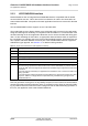


Table Of Contents
- Contents
- Tables
- Figures
- 1 Introduction
- 2 Interface Characteristics
- 2.1 Application Interface
- 2.2 RF Antenna Interface
- 3 Operating Characteristics
- 4 Mechanical Dimensions, Mounting and Packaging
- 5 Regulatory and Type Approval Information
- 6 Document Information
- 7 Appendix

Cinterion
®
PDS5-E/PDS5-US Hardware Interface Overview
2.1 Application Interface
17
PDS5_HIO_v04.000 2018-09-17
Confidential / Preliminary
Page 13 of 35
The figure below shows a circuit to connect an external SIM card holder.
Figure 4: External UICC/SIM/USIM card holder circuit
The total cable length between the SMT application interface pads on PDS5-E/PDS5-US and
the pads of the external SIM card holder must not exceed 100mm in order to meet the specifi-
cations of 3GPP TS 51.010-1 and to satisfy the requirements of EMC compliance.
To avoid possible cross-talk from the CCCLK signal to the CCIO signal be careful that both
lines are not placed closely next to each other. A useful approach is using a GND line to shield
the CCIO line from the CCCLK line.
Module
open: Card removed
closed: Card inserted
CCRST
CCVCC
CCIO
CCCLK
CCIN
SIM /
UICC
1n
220n
SMT application interface
GND