
Product Info
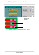
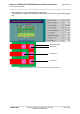
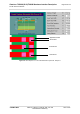


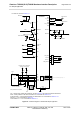
Table Of Contents
- Contents
- Tables
- Figures
- 1 Introduction
- 2 Interface Characteristics
- 2.1 Application Interface
- 2.2 RF Antenna Interface
- 2.3 GNSS Interface
- 2.4 Sample Application
- 3 Operating Characteristics
- 3.1 Operating Modes
- 3.2 Power Up/Power Down Scenarios
- 3.3 Power Saving
- 3.4 Power Supply
- 3.5 Operating Temperatures
- 3.6 Electrostatic Discharge
- 3.7 Blocking against RF on Interface Lines
- 3.8 Reliability Characteristics
- 4 Mechanical Dimensions, Mounting and Packaging
- 5 Regulatory and Type Approval Information
- 6 Document Information
- 7 Appendix
Cinterion
®
TX62-W(-B/-C)/TX82-W Hardware Interface Description
2.4 Sample Application
69
t TX62-W_TX62-W-x_TX82-W_HID_v01.000 2021-10-05
Confidential / Preliminary
Page 69 of 154
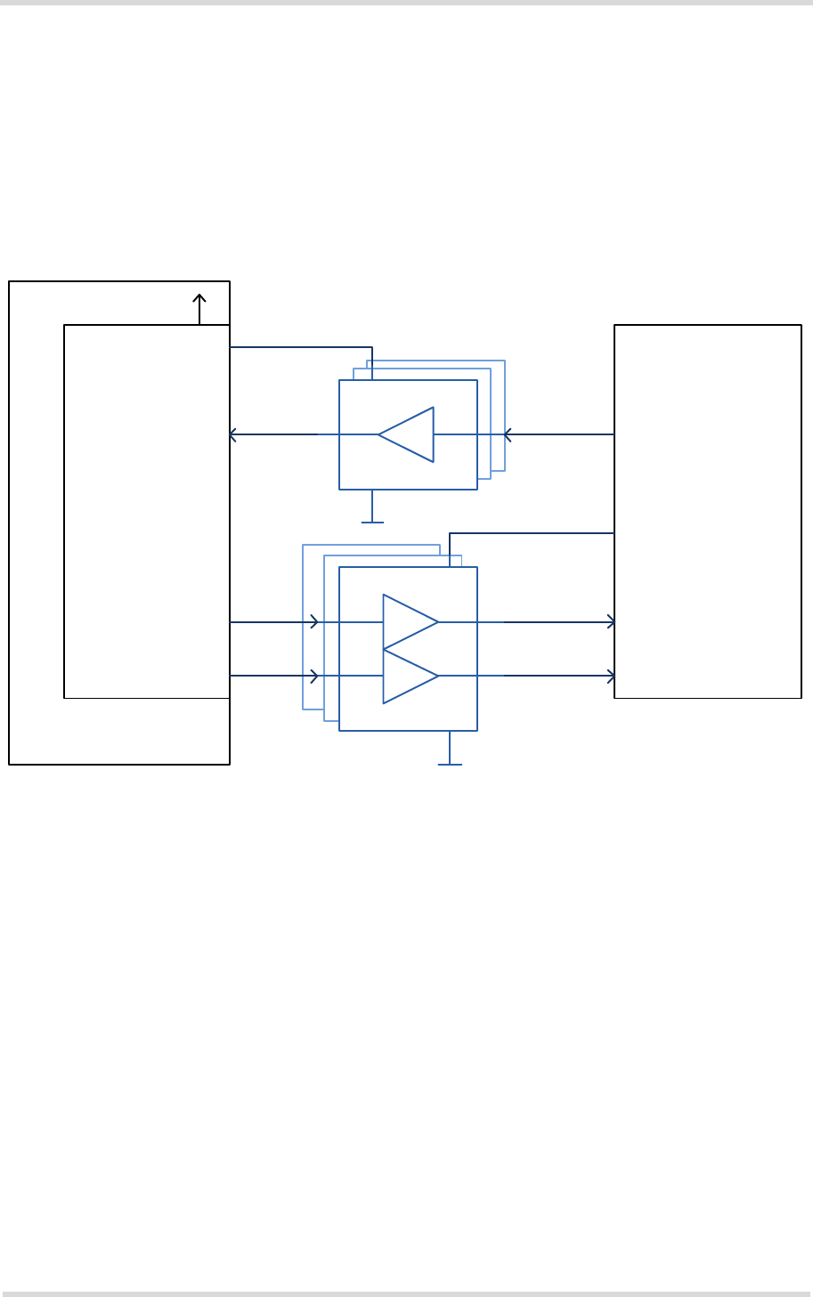
2.4.1 Sample Level Conversion Circuit
Depending on the micro controller used by an external application TX62/TX82‘s digital input
and output lines (i.e., ASC0, ASC1) may require level conversion. The following Figure 33
shows a sample circuit with recommended level shifters for an external application‘s micro con-
troller (with VLOGIC between 3.0V...3.6V). The level shifters can be used for digital input and
output lines with V
OH
max=1.85V or V
IH
max =1.85V. The sample circuit is not optimized for low
current consumption.
Figure 33: Sample level conversion circuit
5V tolerarant
Low level input
Low level input
Low level input
VCC
5V tolerant
VCC
E.g.,
74VHC1GT50
74LV1T34
E.g.,
74LVC2G34
NC7WZ16
External application
Micro controller
VLOGIC
(3.0V...3.6V)
Input lines,
e.g., µRXD, µCTS
Output lines,
e.g., µTXD, µRTS
V180 (1.8V)
Digital output lines,
e.g., RXDx, CTSx
Wireless module
Digital input lines,
e.g., TXDx, RTSx