
Specifications
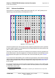
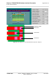
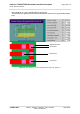
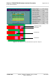
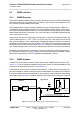
Table Of Contents
- Contents
- Tables
- Figures
- 1 Introduction
- 2 Interface Characteristics
- 2.1 Application Interface
- 2.2 RF Antenna Interface
- 2.3 GNSS Interface
- 2.4 Sample Application
- 3 Operating Characteristics
- 3.1 Operating Modes
- 3.2 Power Up/Power Down Scenarios
- 3.3 Power Saving
- 3.4 Power Supply
- 3.5 Operating Temperatures
- 3.6 Electrostatic Discharge
- 3.7 Blocking against RF on Interface Lines
- 3.8 Reliability Characteristics
- 4 Mechanical Dimensions, Mounting and Packaging
- 4.1 Mechanical Dimensions of TX62-W
- 4.2 Mechanical Dimensions of TX82-W, TX82-W-B, TX62-W-B and TX62-W-C
- 4.3 Mounting TX62/TX82 onto the Application Platform
- 4.4 Packaging
- 5 Regulatory and Type Approval Information
- 6 Document Information
- 7 Appendix

Cinterion
®
TX62-W/TX82-W Hardware Interface Description
2.2 RF Antenna Interface
73
t TX62-W_TX62-W-x_TX82-W-x_HID_v01.200d 2022-09-08
Public / Preliminary
Page 63 of 170
2.2.3 RF Line Routing Design
2.2.3.1 Line Arrangement Examples
Several dedicated tools are available to calculate line arrangements for specific applications
and PCB materials - for example from http://www.polarinstruments.com/ (commercial software)
or from https://www.awr.com/software/options/tx-line (free software).
Embedded Stripline
This figure below shows a line arrangement example for embedded stripline with 65µm FR4
prepreg (type: 1080) and 710µm FR4 core (4-layer PCB).
Figure 27: Embedded Stripline with 65µm prepreg (1080) and 710µm core