
Specifications
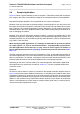
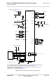
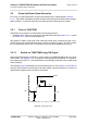
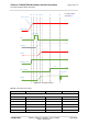
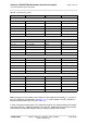
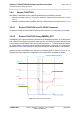
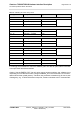
Table Of Contents
- Contents
- Tables
- Figures
- 1 Introduction
- 2 Interface Characteristics
- 2.1 Application Interface
- 2.2 RF Antenna Interface
- 2.3 GNSS Interface
- 2.4 Sample Application
- 3 Operating Characteristics
- 3.1 Operating Modes
- 3.2 Power Up/Power Down Scenarios
- 3.3 Power Saving
- 3.4 Power Supply
- 3.5 Operating Temperatures
- 3.6 Electrostatic Discharge
- 3.7 Blocking against RF on Interface Lines
- 3.8 Reliability Characteristics
- 4 Mechanical Dimensions, Mounting and Packaging
- 4.1 Mechanical Dimensions of TX62-W
- 4.2 Mechanical Dimensions of TX82-W, TX82-W-B, TX62-W-B and TX62-W-C
- 4.3 Mounting TX62/TX82 onto the Application Platform
- 4.4 Packaging
- 5 Regulatory and Type Approval Information
- 6 Document Information
- 7 Appendix

Cinterion
®
TX62-W/TX82-W Hardware Interface Description
3.2 Power Up/Power Down Scenarios
120
t TX62-W_TX62-W-x_TX82-W-x_HID_v01.200d 2022-09-08
Public / Preliminary
Page 79 of 170
3.2.2 Restart TX62/TX82
After startup TX62/TX82 can be re-started as described in the following sections:
• Software controlled reset by AT+CFUN command: Starts Normal mode (see Section
3.2.2.1).
• Hardware controlled reset by EMERG_RST line: Starts Normal mode (see Section 3.2.2.2)
3.2.2.1 Restart TX62/TX82 via AT+CFUN Command
To reset and restart the TX62/TX82 module use the command AT+CFUN. See [1] for details.
3.2.2.2 Restart TX62/TX82 Using EMERG_RST
The EMERG_RST signal is internally connected to the baseband processor. A low level phase
until V180 went low triggers the module restart process, and sets the processor and all signals
to their respective reset states. With a shorter low level phase, i.e., V180 low state not reached,
no module restart is triggered, and the module’s state remains unchanged. The reset state is
described in Section 3.2.3 as well as in the figures showing the startup behavior of an interface.
Please note that if the EMERG_RST signal is not released again as shown in Figure 39, i.e.,
changed from low to high after a restart/reset, the module will be repeatedly restarted.
Figure 39: Emergency restart behavior
T0 T1 T2 T3
BATT+
BB
VCORE
V180
EMERG_RST
Reset state
System restarted
High
High
High
High
For timing values see Table 17.