English Circo G20/G25/G31 Store this document in a safe place 959.044.01.
INSTAL L ATIO N MA N U A L Contents English 1. Introduction 2. CE declaration 3. SAFETY 3.1 General 3.2 Regulations 3.3 Precautions/safety instructions during installation 3.4 Second thermocouple safety 3.5 Oxypilot safety 4. Removing the packaging 5. Installation 5.1 Type of gas 5.2 Gas connection 5.3 Placing the appliance 5.4 Placing a built-in appliance 5.5 Placing the chimney breast 5.6 Placing the control hatch 5.7 Flue gas discharge system in appliances with open combustion 5.7.1 General 5.7.
INST AL L AT I ON M AN U A L 1. Introduction English DRU, a manufacturer of gas-fired heating appliances, develops and produces products that comply with the highest quality, performance and safety requirements. This appliance has a CE label, which means that it complies with the essential requirements of the European gas appliance directive. The appliance is supplied with an installation manual and a user manual. As an installer, you must be certified and competent in the field of gas-fired heating.
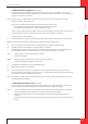
INSTAL L ATIO N MA N U A L 3. SAFETY 3.1 General !Caution - - Please observe the generally applicable regulations and precautions/safety instruction in this manual. First check the exact technical version of the appliance to be installed in Appendix 2, Table 2. 3.2 Regulations English Please install the appliance in accordance with the applicable national, local and constructional (installation) regulations. 3.
INST AL L AT I ON M AN U A L 4. Ø Ø Ø Ø Removing the packaging Note the following items when removing the packaging: Check the appliance and accessories for damages (during transport). If necessary, contact your supplier. Never install an appliance that is damaged ! Remove any screws that are used to fix the appliance to a platform or pallet. English !Caution Heat-resistant glass is a ceramic material.
INSTAL L ATIO N MA N U A L 5. Installation Read this manual carefully to ensure the proper and safe installation of the appliance. !Caution Install the appliance in the order described in this chapter. Ø English Ø Please install the appliance in accordance with the applicable national, local and constructional (installation) regulations. Observe the regulations/instructions in this manual. 5.
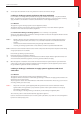
INST AL L AT I ON M AN U A L 5.4 Placing a built in appliance (if applicable) Not all built in appliances by DRU are supplied with a control hatch. If it is not included, this control hatch is available separately. We recommend using the Dru control hatch at all times. In this chapter, it is assumed that the appliance is used with a control hatch. !Caution If you do not use a recommended Dru control hatch, please strictly observe the safeguards and necessary English instructions stated in chapters 5.
INSTAL L ATIO N MA N U A L !Caution When placing the chimney breast, you should take the following into account (see Appendix 3, fig. 2): English - - the location of the control hatch: this must be placed as low as possible; the dimensions of the control hatch; see Placing the control hatch section 5.6; the Dru control hatch is not supplied with all appliances. Nevertheless, we recommend only using a Dru control hatch, which can be supplied separately, if necessary.
INST AL L AT I ON M AN U A L !Tip You can place the outer frame in such a way, that the door turns to the left or to the right. 5.7 Flue gas discharge system in appliances with open combustion English For connection to an existing chimney without a discharge pipe or flexible SS discharge – only allowed in Great Britain – the instructions provided in the separately supplied booklet 'Fitting into a conventional class 1 chimney' apply.
INSTAL L ATIO N MA N U A L 5.8.2 Construction of the concentric system Depending on the construction of the concentric system, the appliance will have to be further adjusted with possibly a restrictor slide or air inlet guide. See Tables 4 and 6 for determining the correct adjustment and section 5.9, Adjustment of the appliance, for the method of working.
INST AL L AT I ON M AN U A L !Caution - When using the wall terminal, place the terminal with a downward slope of 1 cm / metre towards the outside, in order to prevent rain water from raining in. 5.8.4 Connection to an existing chimney English It is possible to connect the appliance to an existing chimney. A flexible SS pipe is placed in the chimney with a fitting diameter at the flue gas discharge pipe, for the discharge of flue gas. The surrounding space is used to supply combustion air.
INSTAL L ATIO N MA N U A L 5.9 Additional instructions !Tip It will be easier to reach the gas control, if you remove the front panel 5.9.1 Placing the appliance When placing the appliance, please take the following aspects into account: Make sure the appliance is stable and level it using the adjustable feet (see Appendix 3, Fig. 5 (K)). !Caution Maintain a minimum distance of 40 mm between the appliance and the back wall (see Appendix 3, Fig. 2). English Ø 5.9.
INST AL L AT I ON M AN U A L 5.10 Glass pane !Caution - - Avoid damaging the pane during removal/placing; Avoid/remove fingerprints on the glass pane, as they will burn into the glass. 5.10.1 Removing the glass pane When removing the front glass pane, you should follow the next steps: Open the left (see Appendix 3, Fig. 5 (C)) and right side panel (D); Loosen the 2 bolts (see Appendix 3, Fig. 8 (P)) of the top panel (G) by a few strokes; !Caution Do not completely remove the bolts.
INSTAL L ATIO N MA N U A L 5.11.2 Restrictor slide English The restrictor slide (R) is supplied separately (see Appendix 3, Fig. 14). It is mounted as follows: Ø Remove the glass pane as described in section 5.10.1; Ø Fully unscrew the 2 bolts of the top panel (see Appendix 3, Fig. 8 (P)); Ø Remove the top panel (G); Ø Unscrew the 2 self-tapping screws of the upper cover plate (see Appendix 3, Fig.
INST AL L AT I ON M AN U A L 6. Wireless remote control The appliance is supplied with a wireless remote control. Controlling the flame height, igniting and switching off take place through a remote control controlling a receiver. Chapter 4, Wireless remote control, in the User Manual describes the operation of the appliance and how you should use the remote control.
INSTAL L ATIO N MA N U A L 7. Final inspection In order to check whether the appliance is working properly and safely, you must perform the following inspections before the appliance is used. 7.1 Gastightness !Caution All connections must be gastight. Check the connections for gastightness. English The gas control can be subjected to a maximum pressure of 50 mbar. 7.2 Gas pressure/line-pressure The burner pressure is set at the factory; see data plate.
INST AL L AT I ON M AN U A L 7.3.2 Main burner - The pilot burner should ignite the main burner within a couple of seconds, and without popping. The main burner(s) must cross the full burner smoothly and without popping and continue to burn. Ø Ø Check operation of the main burner from a cold condition (pilot flame off): After opening the gas valve, the main burner should burn within a few seconds. !Tip When the gas valve is opened, the motor will start to run; this is audible.
INSTAL L ATIO N MA N U A L 8. Maintenance The appliance must be inspected once per year by a skilled installer in the field of gas-fired heating, and repaired if necessary. Check at least whether the appliance is working properly and safely.
INST AL L AT I ON M AN U A L 9. Delivery You must explain to the user how to operate the appliance. You must give him/her instructions on putting it in operation, the safety measures, the operation of the remote control and annual maintenance (see the User Manual). - Ø Ø Ø Tell the user to close the gas tap immediately and contact the installer in case of malfunctions/poor operation.
INSTAL L ATIO N MA N U A L Appendix 1 diagnosis of malfunctions Fires with electronic ignition, fault finding: Ignition and burning Start 2.01 Can pilot be lit? yes 2.06 Pilot can be lit. Does it stay alight? yes 2.08 Does main burner ignite immediately? yes English no no no 2.02 Sparking? 2.07 Check thermocouple system yes 2.03 Only one spark? no 2.
INST AL L AT I ON M AN U A L no 2.14 Does main burner go out after 'some time'? Wiring the black and red extension wire of the 2nd thermocouple is connected to: the 2nd thermocouple (both wires) the receiver (black wire, can be forgotten during installation) earth (red wire) Flame transfer main burner Is flame transfer main burner OK? Flame must heat 2nd couple within approx. 18 sec. (after servomotor starts to run).
INSTAL L ATIO N MA N U A L Malfunction search diagram atmospheric gas-fired heating appliance with electronic ignition: Starting up cycle English Start 1.01 Does receiver beep? yes 1.03 One long 5 second beep, (possibly preceded by 7 short beeps) no no yes 1.02 Receiver Batteries missing or empty. Replace by 4x AA. When replacing batteries short beep: no beep: receiver defective. Replace by new one. Replace rechargeables by alkaline batteries.
INST AL L AT I ON M AN U A L Appendix 2 Number Wood set 1x Installation manual 1x User manual 1x Decoration ring 1x Restrictor slide 1x Hexagonal nut M5 2x Washer 8.
INSTAL L ATIO N MA N U A L Table 2: Technical data Circo English Product name Type of appliance Free-standing Combustion Closed combustion Supply and discharge system Concentric 150/100 Flame protection version Pilot flame with thermocouple 2nd thermocouple safety yes Atmosphere safety no Explosion hatch yes Type C11/C31 Type of gas G20 G25 G31 mbar 14,5 18,2 23,5 Nominal heat input (Hs) kW 9,1 8,2 8,5 Nominal heat input (Hi) kW 8,2 7,4 7,7 Nominal output kW 7,0 6,0
INST AL L AT I ON M AN U A L Country mbar NL / DK / FI / NO / SE / HU / BA / GR 30 FR / BE / IT / PT / ES / GB / IE 37 D 50 English Table 3: Line-pressure when using G31 Permissibility and conditions concentric system with wall terminal Table 4: Conditions for setting the appliance G20/G25/G31 Total number Total number of meters of meters horizontal pipe length vertical pipe (excluding wall length terminal) 1 1) - 4 1 1) - 4 See Air inlet guide Restrictor slide Distance of restriction in mm
INSTAL L ATIO N MA N U A L Permissibility and conditions concentric system with roof terminal G20/G25/G31 Table 5: Determining permissibility concentric system Total number of meters Total no. of meters vertical and/or sloping pipe length horiz.
INST AL L AT I ON M AN U A L Appendix 3 Figures 1 English 150 100 475 372,5 79,5 1041,5 605 442,5 172 38C-1776 35 430 2 4a 4b Min 40 mm 38c-1777 Min 500 mm UK
INSTAL L ATIO N MA N U A L 5 6 English S C 38c-1779 38c-1778 D K 4x 7 Q 38c-1780/1 B T UK
INST AL L AT I ON M AN U A L 8 G English P 38c-1781/1 H A 9 10 R 6x E 38c-1782 F 38c-1783 UK
INSTAL L ATIO N MA N U A L English 11 A A = 38c-1784 12 G H L I 38c-1785 UK A-A =
INST AL L AT I ON M AN U A L 13 English L 38c-1786 14 38c-1787 R J UK
INSTAL L ATIO N MA N U A L 15 16 38P-0265 English 38P-0266 17 18 38p-0022 38p-0023 19 20 38P0113 38P-0273 UK
INST AL L AT I ON M AN U A L English 21 A B C D 38P-0267/0 22 23 A 38P-0268 B 38P-0269 UK
INSTAL L ATIO N MA N U A L English 24 38P-0270 C 25 38P-0271 D UK
INST AL L AT I ON M AN U A L 39 38 c-1 English 38 78 8 40 41 38p-0181 38p-0179 42 43 25 28,7 15 A B A SECTION A-A SCALE 1 : 20 38p-0182 38C-1663/0 5mV UK
English DRU Verwarming B.V.