
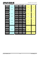
Specifications


.
OG_STD-302N-R_v15e Circuit Design, Inc.
13
OPERATION GUIDE
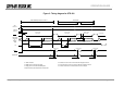
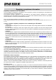
TIMING CHART
Control timing in a typical application is shown in Figure 3.
Initial setting of the port connected to the radio module is performed when power is supplied by the CPU and
reset is completed. MOS-FET for supply voltage control of the radio module, RXSEL and TXSEL are set to
inactive to avoid unwanted emissions. The power supply of the radio module is then turned on. When the
radio module is turned on, the PLL internal resistor is not yet set and the peripheral VCO circuit is unstable.
Therefore data transmission and reception is possible 40 ms after the setting data is sent to the PLL at the
first change of channel, however from the second change of channel, the circuit stabilizes within 20 ms and is
able to handle the data.
Changing channels must be carried out in the receive mode. If switching is performed in transmission mode,
unwanted emission occurs.
If the module is switched to the receive mode when operating in the same channel, (a new PLL setting is not
necessary) it can receive data within 5 ms of switching
*1
. For data transmission, if the RF channel to be used
for transmission is set while still in receiving mode, data can be sent at 5 ms after the radio module is
switched from reception to transmission
*2
.
Check that the Lock Detect signal is “high” 20 ms after the channel is changed. In some cases the Lock
Detect signal becomes unstable before the lock is correctly detected, so it is necessary to note if processing
of the signal is interrupted. It is recommended to observe the actual waveform before writing the process
program.
*1
DC offset may occur due to frequency drift caused by ambient temperature change. Under conditions below
-10 °C, 10 to 20 ms delay of DO output is estimated. The customer is urged to verify operation at low
temperature and optimize the timing.
*2
Sending ‘10101…..’ preamble just after switching to transmission mode enables smoother operation of the
binarization circuit of the receiver. For 9600 bps, a preamble of ‘11001100’ is effective.
Preamble length: -20 °C - +60 °C: 15 ms (Typical)
Remark
For details about PLL control and the sample programs, see our technical document ‘STD-302 interface
method’