
Specifications

OG_STD-302N-R_v15e Circuit Design, Inc.
5
OPERATION GUIDE
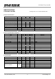
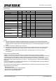
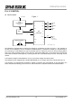
Receiver part
Item MIN TYP MAX Remarks
Receiver type Double superheterodyne
1st IF frequency MHz 21.7
2nd IF frequency kHz 450
Maximum input level dBm 10
BER (0 error/2556 bits)
*1
dBm -107 -110 At 434.05MHz PN 9 9600bps
BER (1 % error)
*2
dBm -116 At 434.05MHz PN 9 9600bps
Sensitivity 12dB/ SINAD dBm -119 fm1 k/ dev 2.75 kHz CCITT
80 1 st Mix, 2 signal method, 1 % error
Spurious response rejection
*3
dB
60 2 nd Mix, 2 signal method, 1 % error
Adjacent CH selectivity
*3
dB 50 +/- 25 kHz, 2 signal method, 1 % error
Intermodulation
*4
dB 50 2 signal method, 1 % error
DO output level V 0 2.8 L = GND H = 2.8 V
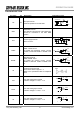
30 50 CH shift of 25 kHz (from PLL setup)
RSSI rising time ms
50 70 When power ON (from PLL setup)
50 100 CH shift of 25 kHz (from PLL setup)
Time until valid Data-out
*5
ms
70 120 When power ON (from PLL setup)
-57 Below 1000 MHz
Spurious radiation dBm
-47 Above 1000 MHz
RSSI mV 180 230 280 With -113 dBm at 434.05MHz
Specifications are subject to change without prior notice
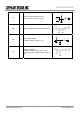
Notice
The time required until a stable DO is established may get longer due to the possible frequency drift
caused by operation environment changes, especially when switching from TX to RX, from RX to TX and
changing channels. Please make sure to optimize the timing. The recommended preamble is more than
20 ms.
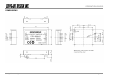
Antenna connection is designed as pin connection.
RF output power, sensitivity, spurious emission and spurious radiation levels may vary with the pattern
used between the RF pin and the coaxial connection. Please make sure to verify those parameters
before use.
The feet of the shield case should be soldered to the wide GND pattern to avoid any change in
characteristics.
Notes about the specification values
*1 BER: RF level where no error per 2556 bits is confirmed with the signal of PN9 and 9600 bps.
*2 BER (1 % error) : RF level where 1% error per 2556 bits is confirmed with the signal of PN9 and 9600 bps.
*3 Spurious response, CH selectivity: Jamming signal used in the measurement is unmodulated.
*4 Intermodulation: Ratio between the receiver input level with BER 1% and the signal level (PN9 9600 bps)
added at the points of 'Receiving frequency - 200 kHz ' + ' Receiving frequency -100kHz' with which BER 1%
is achieved.
*5 Time until valid Data-out : Valid DO is determined at the point where Bit Error Rate meter starts detecting
the signal of 9600bps, 1010repeated signal.
All specifications are specified based on the data measured in a shield room using the PLL setting controller
board prepared by Circuit Design.
Measuring equipment:
SG=ANRITUS communication analyzer MT2605
Spectrum analyzer = ANRITSU MS2663G
BER measure = ANRITSU MP1201G