S/M No. : Service Manual Microwave Oven Model: KOR-1N9Z9S25 ✔ Caution : In this Manual, some parts can be changed for improving, their performance without notice in the parts list. So, if you need the latest parts information, please refer to PPL(Parts Price List) in Service Information Center (http://svc.dwe.co.kr). Jul.
PRECAUTIONS TO BE OBSERVED BEFORE AND DURING SERVICING TO AVOID POSSIBLE EXPOSURE TO EXCESSIVE MICROWAVE ENERGY (a) Do not operate or allow the oven to be operated with the door open.
SAFETY AND PRECAUTIONS CAUTION This device is to be Serviced only by Properly Qualified Service Personel. Consult the Service Manual for Proper Service Procedures to Assure Continued Safety Operation and for Precautions to be Taken to Avoid Possible Exposure to Excessive Microwave Energy. 1. FOR SAFE OPERATION Damage that allows the microwave energy (that cooks or heats the food) to escape will result in poor cooking and may cause serious bodily injury to the operator.
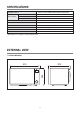
SPECIFICATIONS POWER SUPPLY MICROWAVE 230V AC, 50Hz SINGLE PHASE WITH EARTHING INPUT POWER 1400 W ENERGY OUTPUT 1000 W FREQUENCY 2,450 MHz OUTSIDE DIMENSIONS (W x H x D) 515 x 304 x 376 mm CAVITY DIMENSIONS (W x H x D) 356 x 249 x 359 mm CAVITY VOLUME 31 L NET WEIGHT APPROX. 13.6 Kg TIMER 59 min. 90 sec. POWER SELECTIONS 10 Levels * Specifications are subject to change without notice. EXTERNAL VIEW 1.
2. FEATURES DIAGRAM 1 2 3 67 8 9 w 0 4 q 1 Door latch - When the door is closed, it will automatically shut off. If the door is opened while the oven is operating, the magnetron will automatically shut off. 5 7 Safety interlock system 8 Control panel 9 Door open button - To open the door push the door open button. 2 Door seal - The door seal surfaces prevent microwaves escaping from the oven cavity. 0 Glass cooking tray - Made of special heat resistant glass.
3. CONTROL PANEL e 1 2 4 3 3 5 0 6 9 7 w 8 q 1 Display - Cooking time, power level, indicators and are displayed. 9 Kitchen Timer - Used as a minute timer, delay cooking, hold setting after cooking. 2 Auto cook - Used to cook or reheat. 0 Time set pad - Used to set the cooking time and defrost time. 3 One touch - Used to cook or reheat specific quantities of food. q Stop/Clear - Used to stop the oven operation or to delete the cooking data. 4 More - Used to add time to cooking.
INSTALLATION 1. Steady, flat location This microwave oven should be set on a steady, flat surface. This microwave oven is designed for counter top use only. 2. Leave space behind and side All air vents should be kept a clearance. If all vents are covered during operation, the oven may overheat and, eventually, cause failure. 3. Away from radio, and TV sets Poor television reception and radio interference may result if the oven is located close to a TV, radio, antenna, or feeder and so on.
OPERATIONS AND FUNCTIONS 1. Connect the main lead to an electrical outlet. 2. After placing the food in a suitable container, open the oven door and put it on the glass tray. The glass tray must always be in place during cooking. 3. Close the door securely. 4. When the oven door is opened, the light turns off. 5. The oven door can be opened at any time during operation. The oven will automatically shut off. To restart the oven, close the door and then touch START. 6.
DISASSEMBLY AND ASSEMBLY Cautions to be observed when troubleshooting. Unlike many other appliances, the microwave oven is high-voltage, high-current equipment. It is completely safe during normal operation. However, carelessness in servicing the oven can result in an electric shock or possible danger from a short circuit. You are asked to observe the following precautions carefully. 1. Always remove the power plug from the outlet before servicing. 2.
1. To remove cabinet 1) Remove three screws on cabinet back. 2) Pull the cabinet backward. 2. To remove door assembly 1) Remove two screws which secure the stopper hinge top. 2) Remove the door assembly from top plate of cavity. 3) Reverse the above for reassembly. NOTE : After replacing the door assembly, perform a check of correct alignment with the hinge and cavity front plate.
3. To remove door parts. A06 A05 A04 A03 A02 A01 A07 A08 REF NO. PART CODE PART NAME DESCRIPTION A00 3511731450 DOOR AS KOR-1N9M9P25 1 A01 3517012010 BARRIER-SCREEN *O TEMP GLASS T3.2 PATTERN 1 A02 3512212300 FRAME DOOR ABS SG-0760D,SG-175 1 A03 3515204120 STOPPER HINGE *T AS KOR-6L0B1A 1 A04 3511727500 DOOR PAINTING AS KOR-1N0A9A 1 A05 3517006000 BARRIER-SCREEN *I PE T0.
4. Method to reduce the gap between the door seal and the oven front surface. (1) To reduce gap located on part ‘A’ • Loosen two screws on the stopper hinge top, and then push the door to contact the door seal to the oven front surface. • Tighten two screws. (2) To reduce gap located on part ‘B’ • Loosen two screws on the stopper hinge under, and then push the door to contact the door seal to the oven front surface. • Tighten two screws.
5. To remove control panel parts. B08 B10 B07 B06 B05 B04 B03 B02 B01 B09 B11 B12 B13 REF NO.
6. To remove high voltage capacitor. 1) Remove the screw which secure the grounding ring terminal of the H.V. diode and the capacitor holder. 2) Remove the H.V. diode from the capacitor holder. 3) Reverse the above steps for reassembly. ◆ High voltage circuit wiring 7. To remove magnetron. 1) Remove the screw which secure the magnetron. 2) Remove the magnetron. 3) Reverse the above steps for reassembly.
8. To remove wind guide assembly. 1) Remove the screw for earthing. 2) Remove the noise filter from the wind guide. 3) Remove the screw which secure the wind guide assembly. 4) Draw forward the wind guide assembly. 5) Pull the fan from the motor shaft. 6) Remove two screws which secure the motor shaded pole. 7) Remove the motor shaded pole. 8) Reverse the above steps for reassembly. 9. To remove H.V.transformer. 1) Remove four screws holding the H.V.transformer. 2) Remove the H.V.transformer.
INTERLOCK MECHANISM AND ADJUSTMENT The door lock mechanism is a device which has been specially designed to completely eliminate microwave radiation when the door is opened during operation, and thus to perfectly prevent the danger resulting from the leakage of microwave.
TROUBLESHOOTING GUIDE Following the procedure below to check if the oven is defective or not. 1. Check grounding before trouble checking. 2. Be careful of the high voltage circuit. 3. Discharge the high voltage capacitor. 4. When checking the continuity of the switches, fuse or high voltage transformer, disconnect one lead wire from these parts and check continuity with the AC plug removed. To do otherwise may result in a false reading or damage to your meter.
CONDITION Outlet has proper voltage Fuse does not blow. CHECK RESULT CAUSE REMEDY No Continuity Defective magnetron Replace Check continuity of magnetron Check continuity of power supply cord No Continuity Open power supply cord Replace Normal Defective touch control circuit Replace Malfunction of secondary interlock switch Replace Display do not shown countdown NOTE 1 All these switches must be replaced at the same time, please refer to “Interlock Mechanism And Adjustment”.
(TROUBLE 3) CONDITION No microwave oscillation No microwave oscillation even though fan motor rotates.
(TROUBLE 4) The following visual conditions indicate a probable defective touch control circuit 1. Incomplete segments (1) Segments missing (2) Partical segments missing (3) Digit flickering other than normal display slight flickering (4) “ :0” does not display when press and hold ZERO ON button until display is turned on and beep sounds. 2. A distinct change in the display is not on when it should be. 3. One or more digits in the display are not on when they should be. 4.
MEASUREMENT AND TEST 1. MEASUREMENT OF THE MICROWAVE POWER OUTPUT Microwave output power can be checked by indirectly measuring the temperature rise of a certain amount of water exposed to the microwave as directed below. PROCEDURE 1. A cylindrical container of borosilicate glass is used for the test. It has a maximum thickness of 3mm, an external diameter of approximately 190mm and a height of approximately 90mm. The mass of the container is determined. 2.
2. MICROWAVE RADIATION TEST CAUTION : 1. Make sure to check the microwave leakage before and after repair of adjustment. 2. Always start measuring of an unknown field to assure safety for operating personnel from microwave energy. 3. Do not place your hands into any suspected microwave radiation field unless the safe density level is known. 4. Care should be taken not to place the eyes in direct line with the source of microwave energy. 5.
3. COMPONENT TEST PROCEDURE • High voltage is present at the high voltage terminal of the high voltage transformer during any cooking cycle. • It is neither necessary nor advisable to attempt measurement of the high voltage. • Before touching any oven components or wiring, always unplug the oven from its power source and discharge the capacitor. 1. High voltage transformer (1) Remove connections from the transformer terminals and check continuity.
N L GE BL FUSE FILTER ASS'Y N BR L POWER SUPPLY : SINGLE PHASE ONLY GN N L RD THERMOSTAT WH 23 POWER SWITCH RD BK NOTE : RD : RED WH : WHITE BK : BLACK GN : GREEN BR : BROWN RD 3 1 WH GY GY OR : ORANGE BL : BLUE GY : GRAY GE : GREEN/YELLOW BL BL DOM SWITCH RELAY-1 RELAY-2 RELAY-3 CONTROL P.W.B.
PRINTED CIRCUIT BOARD 1. CIRCUIT CHECK PROCEDURE 1. Low Voltage Transformer check • The low voltage transformer is located on the P.C.B. • Measuring condition: input voltage : 230V / Frequency : 50Hz Terminal Voltage LOAD NO LOAD (4,5)-6 or (7,8)-6 AC 25.3 V AC 30.8 V NOTE : 1. Refer to Circuit Diagram (point 4). 2. Secondary side voltage of the low voltage transformer changes in proportion to fluctuation of power source voltage. 3.
MP1 MP2 GND Measure Point 25
3. When there is no microwave oscillation 1) When touching Start/+30sec. pad, oven lamp does not turn on. Fan motor do not rotate, but cook indicator in display comes on. B A RY2 42 D10 (TRAY LAMP) Q10 RY2 - Check method POINT A B RELAY 2 ON 5VDC GND RELAY 2 OFF GND 15VDC STATE 2) When touching Start/+30sec. pad, oven lamp turns on. Fan motor and turntable rotate and cook indicator in display comes on.
27 NOTE SJ4 SJ1 30min H.V.Trans :INSERT SJ6 0~9 (KEY) 10,1,10(KEY) SJ2 :REMOVAL SJ5 g Lb SJ3 CN3 YW396-07AV 1 2 3 4 POWER SAVE PART LVT1 DMR-631P/ DMR-631FS 7 6 4,5 D13 R10 1K R22 1K KN4004A D14 D9 1N4148 EC2 1000uF 25V R21 51 1/4W D10 1N4148 51 1/4W D6 1N4148 R24 D8 1N4148 + - R20 10K D11 1N4148 V2 C1 104Z V1 V1 + EC1 10uF - 50V R1 1K V R15 R16 G R18 1K R17 1K R14 1M C3 102K R13 1K V1 C6 104Z C5 C4 102K 104Z V1 Q10 KRC106M Q7 KRC106M CR1 4.
3. PCB LOCATION NO.
EXPLODED VIEW AND PARTS LIST 1. DOOR ASSEMBLY Refer to Disassembly and assembly. 2. CONTROL PANEL ASSEMBLY Refer to Disassembly and assembly. 3.
REF NO.
DAEWOO ELECTRONICS CORP. 1-2, Jeo-dong 1(il)-ga, Jung-gu, Seoul, Korea C.P.O. BOX 8003 SEOUL, KOREA TELEX: DWELEC K28177-8 CABLE: “DAEWOOELEC” S/M NO. : PRINTED DATE: Jul.
ABOUT THIS MANUAL vision@creativeL@incN Էܞ ړĸ ࣃۉʷ VѨێ ݖΟӂ˱ Tࠚ ɽ ʁ ŇېՁ ɮ m@o@d@e@l korMQnYzYsRU@HsOmI ܂ RPQRNPSNRY ր memo@@߭ SS QRNPWNQPM֭ߘ۾Ŕ SS QRNPWNQQMRXL@RY@ր֭@܄Ŕ R QRNPWNQRMYL@QWL@RPL@RUL@RW@ր֭@܄Ŕ U QRNPWNQXMQL@SL@THच ݖێԔ܆IL@RS@ր֭@܄Ŕ T ِ͊ߏ vision ɽ ʁ і О ր telZ WSPMPVVP@faxZ WSPMSWXX