
Service manual

12
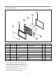
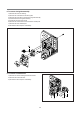
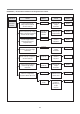
5. To remove control panel parts.
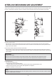
B02
B03
B10
B11
B12
B13
B04
B05
B06
B07
B01
B08
B09
(1) Remove the screw which secure the control panel, push up two snap fits and draw forward the control panel assembly.
(2) Remove three screws which secure the PCB assembly to the control panel.
(3) Disconnect membrane tail from the connector of the PCB assembly.
(4) Remove the PCB from the control panel.
(5) Remove the membrane, lever door open, spring button and button door open from the control panel.
(6) Reverse the above steps for reassembly.
B00 PKCPSWYS60 CONTROL-PANEL AS KOR-1N9Z9S25 1
B01 3511633320 DECORATOR RING ABS SG-0760D SG-175 COATING 1
B02 3518573580 SWITCH MEMBRANE KOR-1N9Z9S 1
B03 3516743600 CONTROL-PANEL ABS SG-0760D,SG-175 1
B04 3516922800 BUTTON STANDBY SG-0760D,SG-175 1
B05 5S732G30X0 SW MICRO MS2-T0T200 250/125V 5A T85 1
B06 3513006300 HOLDER STANDBY SW PP 1
B07 7121300611 SCREW TAPPING T2S PAN 3X6 MFZN 1
B08 3512785410 HARNESS SWITCH MICRO KOR-1N9M9V 1
B09 PKMPMSZZ14 PCB MAIN MANUAL AS KOR-1N9Z9S25 1
B10 7122401211 SCREW TAPPING T2S TRS 4*12 MFZN 3
B11 3513702700 LEVER DOOR OPEN PP 1
B12 441G430171 SPRING BUTTON SWP DIA. 0.7 1
B13 3516922900 BUTTON DOOR OPEN ABS SG-0760D,SG-175 1
REF NO. PART CODE PART NAME DESCRIPTION Q’TY REMARK