
Instructions
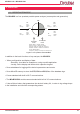

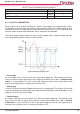
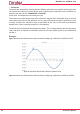
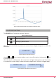
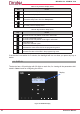
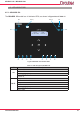
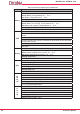
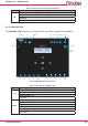
Table Of Contents
- Safety precautions
- DISCLAIMER
- CONTENTS
- Revision log
- SYMBOLS
- 1.- VERIFICATION UPON RECEPTION
- 2.- Product description
- 3.- DEVICE installation
- 3.1.- PRELIMINARY RECOMMENDATIONS
- 3.2.- BATTERY INSTALLATION
- 3.4.- MYeBOX 480V ~ PSU ADAPTER : POWER SUPPLY ADAPTER
- 3.5.- VOLTAGE CABLES
- 3.6.- CURRENT CLAMPS
- 3.7.2.- MYeBOX 1500
- 3.8.- CONNECTION DIAGRAMS
- 3.8.1.- Three-phase network measuring with a 4-wire connection,
- MYeBOX 150.
- 3.8.2.- Three-phase network measuring with a 4-wire connection,
- MYeBOX 1500.
- 3.8.3.- Three-phase network measuring with a 3-wire connection, MYeBOX 150 and MYeBOX1500.
- 3.8.4.- Three-phase network measuring with a 3-wire connection and ARON connection, MYeBOX 150 and MYeBOX 1500.
- 3.8.5.- Two-phase network measuring with a 3-wire connection,
- MYeBOX 150.
- 3.8.6.- Two-phase network measuring with a 3-wire connection,
- MYeBOX 1500.
- 3.8.7. - Single-phase network measurement, phase to phase, with a 2-wire connection, MYeBOX 150 and MYeBOX 1500.
- 3.8.8.- Single-phase network measurement, phase to neutral, with a 2-wire connection, MYeBOX 150.
- 3.8.9.- Single-phase network measurement, phase to neutral, with a 2-wire connection, MYeBOX 1500.
- 3.8.10.- Detail of the current measurement connection.
- 3.8.11.- Leakage current connection, ILeak. (MYeBOX 1500 model)
- 3.9.- REGISTERING AND UPDATING THE DEVICE
- 4.- OPERATION
- 5.- display
- 6.- CONFIGURATION
- 6.2.2.- Measurement name
- 6.2.1.- Name of the device
- 6.1.12.- Exit
- 6.1.11.- Save
- 6.1.10.- Frequency
- 6.1.9.- Primary winding of the leakage current transformer
- 6.1.7.- Primary winding of the neutral current transformer
- 6.1.6.- Neutral clamp scale
- 6.1.5.- Primary winding of the current transformer
- 6.1.4.- Phase clamp scale
- 6.1.3.- Secondary voltage
- 6.1.2.- Primary voltage
- 6.3.2.- Gap, Sag
- 6.3.1.- Overvoltage, swell
- 6.2.5.- Exit
- 6.2.4.- Save
- 6.2.3.- Type of installation
- 6.4.1.- Wi-Fi Configuration
- 6.3.6.- Exit
- 6.3.5.- Save
- 6.3.4.- Transients, Disturb
- 6.3.3.- Outage, Interruption
- 6.4.9.- PIN
- 6.4.8.- APN, password
- 6.4.7.- APN, user
- 6.4.6.- APN, access point name
- 6.4.5.- Enabling 3G communications
- 6.4.4.- Password
- 6.4.3.- WPS
- 6.4.2.- SSID
- 6.5.- SETUP MENU: MEMORY SETUP
- 6.6.- SETUP MENU: RESET FACTORY SETUP
- 6.1.1.- Rated voltage
- 6.1.8.- Clamp scale for measuring the leakage current, ILeak
- 7.- WIRELESS COMMUNICATIONS
- 8.- MOBILE APPLICATION MYeBOX
- 9.- mYeBOX Cloud
- 10.- software UPDATE
- 11.- TECHNICAL FEATURES
- 12.- Maintenance AND TECHNICAL SERVICE
- 13.- GUARANTEE
- 14.- CE CERTIFICATE

32
MYeBOX 150 - MYeBOX 1500
Instruction Manual
4.2.- MEASUREMENT PARAMETERS
The device measures and logs different types of parameters:
Electrical parameters,
Quality parameters (EVQ) such as overvoltages, gaps and outages, in accordance with
EN50160.
Wave shapes of the different channels.
All the measurement parameters can be viewed on the MYeBOX mobile application, as shown
in Table 11.
Table 11: MYeBOX measurement parameters�
Parameter Units
Phases
L1-L2-L3
N
Total
III
Phase-neutral voltage
(12)
Vph-N
Phase-phase voltage
(12)
Vph-ph
Current
(12)
A
Leakage current A
Frequency
(12)
Hz
(L1)
Active power
(12)
kW
Apparent power
(12)
kVA
Inductive reactive power
(12)
kvarL
Capacitive reactive power
(12)
kvarC
Power factor
(12)
PF
Crest factor CF
K-factor -
Cos φ
(12)
φ
Voltage THD % % THD V
Current THD % % THD A
Harmonic Breakdown - Voltage(up to the 50th order harmonic)
harm V
Harmonic Breakdown - Current (up to the 50th order harmonic)
harm A
Instantaneous icker
Pinst
PST Flicker
Pst
Active energy kWh
Inductive Reactive Energy kvarLh
Capacitive Reactive Energy kvarCh
Apparent energy kVAh
Voltage unbalance
(12)
-
Voltage asymmetry
(12)
-
Current unbalance -
Current asymmetry -
Maximum Current Demand A
Maximum Demand for Active Power kW
Maximum Demand for Apparent Power kVA
Wave shapes -
Phasor representation -