
Instructions
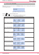
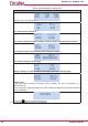
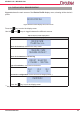
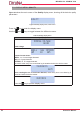
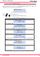
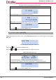

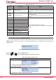
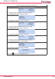

Table Of Contents
- Safety precautions
- DISCLAIMER
- CONTENTS
- Revision log
- SYMBOLS
- 1.- VERIFICATION UPON RECEPTION
- 2.- Product description
- 3.- DEVICE installation
- 3.1.- PRELIMINARY RECOMMENDATIONS
- 3.2.- BATTERY INSTALLATION
- 3.4.- MYeBOX 480V ~ PSU ADAPTER : POWER SUPPLY ADAPTER
- 3.5.- VOLTAGE CABLES
- 3.6.- CURRENT CLAMPS
- 3.7.2.- MYeBOX 1500
- 3.8.- CONNECTION DIAGRAMS
- 3.8.1.- Three-phase network measuring with a 4-wire connection,
- MYeBOX 150.
- 3.8.2.- Three-phase network measuring with a 4-wire connection,
- MYeBOX 1500.
- 3.8.3.- Three-phase network measuring with a 3-wire connection, MYeBOX 150 and MYeBOX1500.
- 3.8.4.- Three-phase network measuring with a 3-wire connection and ARON connection, MYeBOX 150 and MYeBOX 1500.
- 3.8.5.- Two-phase network measuring with a 3-wire connection,
- MYeBOX 150.
- 3.8.6.- Two-phase network measuring with a 3-wire connection,
- MYeBOX 1500.
- 3.8.7. - Single-phase network measurement, phase to phase, with a 2-wire connection, MYeBOX 150 and MYeBOX 1500.
- 3.8.8.- Single-phase network measurement, phase to neutral, with a 2-wire connection, MYeBOX 150.
- 3.8.9.- Single-phase network measurement, phase to neutral, with a 2-wire connection, MYeBOX 1500.
- 3.8.10.- Detail of the current measurement connection.
- 3.8.11.- Leakage current connection, ILeak. (MYeBOX 1500 model)
- 3.9.- REGISTERING AND UPDATING THE DEVICE
- 4.- OPERATION
- 5.- display
- 6.- CONFIGURATION
- 6.2.2.- Measurement name
- 6.2.1.- Name of the device
- 6.1.12.- Exit
- 6.1.11.- Save
- 6.1.10.- Frequency
- 6.1.9.- Primary winding of the leakage current transformer
- 6.1.7.- Primary winding of the neutral current transformer
- 6.1.6.- Neutral clamp scale
- 6.1.5.- Primary winding of the current transformer
- 6.1.4.- Phase clamp scale
- 6.1.3.- Secondary voltage
- 6.1.2.- Primary voltage
- 6.3.2.- Gap, Sag
- 6.3.1.- Overvoltage, swell
- 6.2.5.- Exit
- 6.2.4.- Save
- 6.2.3.- Type of installation
- 6.4.1.- Wi-Fi Configuration
- 6.3.6.- Exit
- 6.3.5.- Save
- 6.3.4.- Transients, Disturb
- 6.3.3.- Outage, Interruption
- 6.4.9.- PIN
- 6.4.8.- APN, password
- 6.4.7.- APN, user
- 6.4.6.- APN, access point name
- 6.4.5.- Enabling 3G communications
- 6.4.4.- Password
- 6.4.3.- WPS
- 6.4.2.- SSID
- 6.5.- SETUP MENU: MEMORY SETUP
- 6.6.- SETUP MENU: RESET FACTORY SETUP
- 6.1.1.- Rated voltage
- 6.1.8.- Clamp scale for measuring the leakage current, ILeak
- 7.- WIRELESS COMMUNICATIONS
- 8.- MOBILE APPLICATION MYeBOX
- 9.- mYeBOX Cloud
- 10.- software UPDATE
- 11.- TECHNICAL FEATURES
- 12.- Maintenance AND TECHNICAL SERVICE
- 13.- GUARANTEE
- 14.- CE CERTIFICATE

51
Instruction Manual
MYeBOX 150 - MYeBOX 1500
5.1.- DISPLAY MENU: MEASURE
Figure 42 shows the main screen of the Measure display menu, showing all the device’s
measuring parameters.
MEASURE
Figure 42:Measure display menu, main screen�
Press the key to enter the display menu.
Use the and keys to toggle between the different screens.
Table 22: Measure display menu�
Measure display menu
230.0 230.0 230.0
VL1 VL2 VL3
Phase - Neutral Voltages, VL1, VL2 and VL2
398.0 400.0 401.3
VL12 VL23 VL31
Phase - Phase Voltages, VL12, VL23 and VL31
5.00 5.00 5.00
A1 A2 A3
Phase currents, A1, A2 and A3.
11500 11575 11600
kW1 kW2 kW3
Active Power, of each of the phases�
(16)
11500 11575 11600
kvrL1 kvrL2 kvrL3
Inductive Reactive Power, of each of the phases�
(16)
11500 11575 11600
kvrC1 kvrC2 kvrC3
Capacitive Reactive Power, of each of the phases�
(16)
11500 11575 11600
kVA1 kVA2 kVA3
Apparent Power, of each of the phases�
(16)