HN-2010 Repeater User’s Guide 5375 Oakbrook Parkway Norcross, Georgia 30093 www.cirronet.
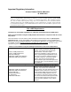
Important Regulatory Information Cirronet Product FCC ID: HSW-2410 IC 4492A-2410 Note: This unit has been tested and found to comply with the limits for a Class A digital device, pursuant to part 15 of the FCC Rules. These limits are designed to provide reasonable protection against harmful interference when the equipment is operated in a commercial environment.
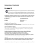
Declaration of Conformity Warning! The RLAN transceiver within this device uses a band of frequencies that are not completely harmonized within the European Community. Before using, please read the European Operation Section of the Products User’s Guide for limitations. 0889 is the identification number of RADIO FREQUENCY INVESTIGATION LTD - Ewhurst Park, Ramsdell RG26 5RQ Basingstoke, United Kingdom – the Notified Body having performed part or all of the conformity assessment on the product.
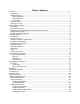
Table of Contents Overview .......................................................................................................................................1 Introduction ................................................................................................................................1 HopNet Products .......................................................................................................................1 External Antenna....................................................
Set Transmit Power.............................................................................................................29 Read Receive Signal Strength Indicator (RSSI) .................................................................29 Set Point-to-Point Direct Mode............................................................................................29 Set Range Optimization ......................................................................................................
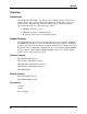
HN-2010 Overview Introduction The HopNet 10 Series family of products provides reliable wireless connectivity for either point-to-point or point-to-multipoint applications. The HopNet products are built around the WIT2410 radio transceiver, which employs frequency hopping spread spectrum technology.
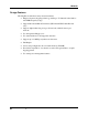
HN-2010 Design Features The HopNet modems have many advanced features: • Employ frequency hopping technology with up to 75 channels in the 2401 to 2475 MHz frequency range • Support RS-232 and RS 485 interfaces (HN-210 and HN-510 are RS-232 only) • Support digital addressing for up to 64 networks, with 62 remotes per network.
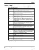
HN-2010 Glossary of Terms Refer to the following list of terms that may be unfamiliar to you. These terms are used throughout this document. Definition Term ARQ Automatic Repeat Request. The operation in which the radio will re-send the data until it is received correctly. bps Bits-per-second. A measure of information transfer rate of digital data across a channel. Decibel A measure of the ratio between two signal levels. Used to express either loss or gain.
HN-2010 About HopNet Products Introduction This section provides operational information about the HopNet products. Operating Frequency The HopNet family operates in the 2.4 GHz ISM band that allows for license-free use and worldwide compliance. HopNet Frequency Hopping Spread Spectrum Advantages In the frequency domain, a multipath fade can be described as a frequency selective notch that shifts in location and depth over time. Multipath fades typically occupy five percent of the band.
HN-2010 HN-2010 Repeater Introduction The HopNet Repeater (HN-2010) provides extended range capability between two HopNet networks. This repeater capability allows HopNet networks to be “daisychained” in series to send and receive data from remote locations that would otherwise be outside the coverage area of a single network. If a remote unit is unable to communicate with the Base because of distance or obstruction, you can install a repeater.
HN-2010 Antenna and Power Connections There are three external connections going into the repeater enclosure and one internal connection: • Two RF ports • A 2-pin Conxall power connector • An internal DB-9 connector RF Antenna Connectors The two RF antenna connectors are standard female TNC. These ports connect to the output of each internal modem. You can attach remote antenna cables to these connectors.
HN-2010 DB-9 Connector The DB-9 connector is located inside the back panel of the enclosure and is used to configure the HN-2010. See the illustration below for the pin-out of the DB-9 connector. Three-Way Switch A miniature 3-way switch is located inside the back panel of the enclosure. See the illustration below.
HN-2010 LED Status Three external LEDs are on the front panel to inform you of the status of the repeater. The following illustration shows the three LEDs. Refer to the following table for a description of the LEDs. Name Color Description PWR Green Continuous DC power is applied RXD Amber Received Data of base unit CD Amber Data Carrier Detect of remote unit An additional LED is installed inside the unit to help you configure the transceivers.
HN-2010 Antenna Connectors The external antenna connectors are located on the front panel and are female TNC connectors. See the illustration below. Proper placement of the external antenna is important since two modems inside the HN-2010 will be operating simultaneously. Be sure to physically separate the antennas from each other because the output transmission of one side of the repeater may interfere with the reception of the other.
HN-2010 Configuring the Repeater Complete these steps to configure the HN-2010 Repeater to the desired mode: 1. Remove the back panel of the repeater to set the function. Once the panel is removed, you should see the following: • A DB-9 connector • A 3-way switch • An LED 2. Check the bicolor LED that is directly behind the switch to be sure that it indicates which configuration mode has been selected and which unit is being configured. The LED indicator works with the 3-way switch as follows: 3.
HN-2010 Technical Specifications Refer to the following tables for the technical specifications for the HN-2010.
HN-2010 Mechanical Specification Value Case • NEMA 4X, IP 66 Size • • 8.4 in. x 5.65 in. x 3.0 in. 213mm x 143.5mm x76mm (including mounting flange and connectors) Weight • • 3.
HN-2010 Configuring the Network Overview Introduction You can configure the HopNet network using a PC and the WinCom 24 software provided by Cirronet, Inc. WinCom24 is a software package that runs under Windows 95/98/NT/2000/XP. This chapter provides the information you need to configure your network. The HN-2010 is shipped from the factory initially configured as a remote with a 9600k baud rate.
HN-2010 WinCOM Provided with the developer’s kit is a configuration program designed especially for Cirronet’s wireless industrial transceivers or WIT radios. WinCOM is located on the Manuals and Software CD included in the developer’s kit. Install WinCOM by navigating to the Software Tools directory on the Manuals and Software CD and double-click on wincom2.1.exe follow the installation wizard. Once it has installed, open WinCOM by double-clicking on the WinCOM icon on the desktop.
HN-2010 WinCom’s menu structure is typical of Windows conventions with File, Edit, Options, Tools and Help selections. Under File, Save Settings (Ctrl S) saves the current WinCom settings to the hard drive, Print (Ctrl P) sends whatever text is in the display field to the printer and Exit terminates the program. Under Edit, Copy, Paste, Find (search) and Select All perform the familiar Windows functionality in typical fashion.
HN-2010 Starting the program When started, WinCOM de-asserts and re-asserts the DTR line to the radio which resets the radio causing the sign-on banner to be displayed. If the baud rate on the computer doesn’t match the baud rate of the radio, illegible characters will be displayed. By hitting the PgUp or PgDn key to change the baud rate, then pressing F1 twice to toggle DTR (resets the radio) and causes a new banner to be displayed.
HN-2010 To change configuration parameters, the radio must be put into configuration mode by clicking on the Config Mode button on the WinCOM window immediately after opening WinCOM or after cycling power to the radio. Another method is to toggle the DTR by pressing the F1 key twice, which de-asserts then re-asserts DTR, then pressing the F3 key (or Config Mode button). When the radio is in configuration mode, a “>” prompt character is displayed in the WinCom window as shown above.
HN-2010 If the other radio is sending data, the received data will be displayed in the WinCOM window. If the Binary box is checked, all characters received will be displayed subject to the limitations of Windows. For example, a carriage return will not return the cursor to the left side of the window but the character corresponding to 0xd value of the carriage return will be displayed. Similarly, if the Hex Mode box is checked, all characters are displayed in hexadecimal format.
HN-2010 Function Keys All of the function key shortcuts are described below: F1 — Toggles state of DTR (Sleep). State is shown in status line. F2 — Toggles state of RTS. State is shown in status line. F3 — Transmits “:wit2400”. Used to enter control mode. F5 — Toggles local echo. If you are transmitting characters through one modem to another WIT2450, this allows you to see what you are typing. F6 — Toggles stream mode. Causes WinCOM to transmit a repeating pattern of characters. Useful for testing.
HN-2010 WinCom Tools There are seven selections under the Tools menu. The first, Obey CTS is useful when just a three wire connection is made between the radio and the computer. Some PCs let the CTS input line float. If CTS is not asserted, the PC COM port will not send data. Note: Unchecking this selection will have the PC COM port ignore the state of CTS and transmit data. When WinCOM’s transmit mode is used, data is sent continuously until the user stops it by clicking on Stop or pressing F6.
HN-2010 The fourth, Transmit Tools allows for testing of the Transparent, WIT2410/WIT910 or WIT2411 settings. Parameters related to how the transmission will take place can be set including Handle, Transmit Period, whether or not a Sequence Number should be added, if the Transmission will be continuous or one time, if the data should be sent in Hex Format and whether or not data can be received.
HN-2010 WinCOM has the ability to perform any function or sequence of functions WinCOM can perform through a script file. A script file is a text file that contains one or more commands and arguments save with a wcr filename extension. Each command is separated by a carriage return and linefeed. Configuration commands need to have wait periods between them.
HN-2010 This script file sets the baud rate of the PC COM that WinCOM is using to 115,200 kbps, de-asserts DTR, waits 200 milliseconds, asserts DTR, waits 200 milliseconds, sends the configuration mode escape sequence, waits 200 milliseconds and then sends the m! command to the radio. What this script file does is set the PC COM port baud rate to 115.2 kbps, puts the radio in config mode and the issues the command to display all of the radio parameters that have been changed from factory default.
HN-2010 Finally, the eighth tool is Save to File which launches a Save As dialog that allows any data received to be loaded into a file.
HN-2010 Demonstration Procedure The procedure below provides a quick demonstration of the WIT241x. 1. Attach a transceiver to each computer, preferably between 5' and 30' apart for convenience. 2. Start WinCOM running on both computers If you prefer, almost any other serial communications program such as Procomm or QModem set for 9600 bps will also work. 3.
HN-2010 Modem Commands The HopNet is configured and controlled through a series of commands. These commands are sent to the modem directly when the modem is in Control Mode or when the modem is in Data Mode if the escape sequence is enabled. The command syntax is the same for either method, a one- or two-letter command followed by one or more parameters. The modem will respond with a two-byte message that indicates the new modem parameter value.
HN-2010 Set Data Rate Divisor Sets the serial bit rate between the modem and the host. This command takes effect immediately and will require adjusting the host serial rate to agree. Nonstandard rates may be programmed by entering a data rate divisor computed with the following formula: DIVISOR = (230400/RATE)-1 Round all non-integer values down. Set Protocol Mode Enables the base station to operate in a multipoint network.
HN-2010 Network Commands Network commands are used to set up a HopNet network and to set radio addressing and configuration.
HN-2010 Enable Global Network Mode For networks with multiple base stations, remotes are ordinarily only able to link to one base station, set by the hopping pattern. Mode 1 enables the global mode that allows remotes to link to any base station they can hear, acquiring whatever hop pattern is required. In this mode a remote can only change base stations once it is no longer registered with a base station.
HN-2010 Set Range Optimization This command applies an adjustment factor to the over-the-air timing of remotes to compensate for the effects of propagation delay at long ranges. The default setting of 00H is suitable for ranges of 0 to 0.8 miles (1287 m), with optimal performance at 0.1 miles (162m). Each increment of this parameter adds 0.1 miles (162 m) to the working range. Thus the optimal and max ranges are determined by: optimal = 0.1mi + 0.1mi x dx = 0.17km + 0.17km x dx max = 0.8mi + 0.
HN-2010 Protocol Commands These commands can be used to tune the transceiver for optimum transmission of data across the RF link. For most applications, the default values are adequate. Command pe[?|0-4] Description Set Alternative Frequency Band 0 = FCC/ETSI operation.
HN-2010 Set Alternative Frequency Band When set to 1, limits the operating RF channel set to the 2448 to 2473MHz frequency band for compliance with French regulatory standards. When set to 2, sets appropriate operation for Spain. When set to 3, sets appropriate operation for Japan. This setting should be set to 0, for FCC-compliant operation in the US (this is the default). For Canadian operation, set this parameter to 4.
HN-2010 Set Maximum Number of Remotes (base only) This parameter limits the number of remotes that can register with a given base. The default is 62 remotes which is the maximum number of remotes that can be registered with a base at one time. This command is useful when used in conjunction with global roaming for load balancing when base stations are collocated. It is also useful to assure a minimum remote throughput.
HN-2010 Set Base Slot Size (base station only) Sets the amount of time allocated for transmission on each hop for the base station time slot in 69.4µs increments, corresponding to 4 bytes per unit. Maximum value is 34H which corresponds to 208 bytes. If using a protocol mode, attempting to send a packet with a length longer than this setting will cause the packet to be discarded. Set ARQ Mode Sets ARQ mode when set to 0 which is the default.
HN-2010 Status Commands These commands deal with general interface aspects of the operation of the HopNet. Command Description zb[?|0|1] Banner Display Disable 0 = disabled 1 = enabled (default) zc[?|0..2] Set Escape Sequence Mode 0 = disabled 1 = once after reset (default) 2 = unlimited times zh? Read factory serial number high byte. zm? Read factory serial number middle byte. zl? Read factory serial number low byte.
HN-2010 Read Factory Serial Number High, Middle and Low Bytes. These read only commands return one of the three bytes of the unique factory-set serial number, which are also visible in the startup banner. Set Duty Cycle Allows reduced power consumption by having a remote wake up only every 2N hops to receive and transmit. Power consumption is roughly proportional to the duty cycle selected. For example, if N=2, the remote will wake up every fourth hop.
HN-2010 Memory Commands The user is able to store a configuration in nonvolatile memory, which is loaded during the initialization period every time the radio is powered up. Note that changes to the serial port baud rate- from recalling the factory defaults or recalling memory will not take effect until DTR is toggled or power to the radio is cycled.
HN-2010 Modem Command Summary Serial Commands sd[?|00..ff] sp[?|00..14] Set Data Rate Divisor Set Protocol Mode Network Commands wb[?|0|1] wd[?|1..3f] wn[?|00..3f] wg[?|0|1|2] wp[?|0|1] wr? wu[?|0|1] dx[?|0..62] Set Transceiver Mode Set Default Handle Set Hopping Pattern Enable Global Network Modes Set Transmit Power Read Receive Signal Strength (remote only) Set Point-to-Point Direct Mode Set Range Optimization (remote only) Protocol Commands pe[?|0..4] ph[?|00..fe] pl? pn[?|01..3e] pk[?|00..
HN-2010 Guidelines for Installation When installing your system, always consider the following points: • Directional antennas are best for remote unit sites. They may increase the cost, but they confine the transmission path to a narrow lobe and minimize the interference from nearby stations. • For systems with constant interference present, you may need to change the polarity of the antenna system and reduce data streams.
HN-2010 Typical HopNet Applications Introduction The illustration below shows a complete network of multiple data sources connected to a central base. Units that are out of range are connected through a repeater. See the illustration of a point-to-point application on the next page. Point to Multipoint This common application consists of a central host and remote terminal units or other data collection devices.
HN-2010 Troubleshooting Overview Introduction Troubleshooting the HopNet products is not difficult, but it does require a logical approach. It is best to begin troubleshooting at the base station because the rest of the system synchronizes to it. If the base station has problems, the entire network will be compromised. This chapter provides troubleshooting information for your HopNet products.
HN-2010 Common System Problems The following table offers suggestions for resolving some common system problems that the operator may experience from the radio system. If problems persist, contact the factory for further assistance. Problem System Checks Unit is inoperative 1. Check for proper DC voltage at the power connector. 2. Momentarily remove and reapply power. No Carrier Detect at remote units or intermittent 1. Check for secure interface connections at the transceiver. 2.
HN-2010 Guidelines for Reducing Interference Introduction The transceivers share the same frequency spectrum with other services and other Part 15 devices in the US. Because of this, you may not achieve 100 percent error free communications in a given location. You should also expect some level of interference.
HN-2010 Guidelines for Avoiding Terrain Obstructions The HopNet transceivers operate in the 2.4 GHz frequency band. While this band offers many advantages over the VHF band for data transmission, it is also more prone to signal attenuation from obstructions such as terrain, foliage, buildings and anything else in the transmission path.
HN-2010 Customer Support Introduction Cirronet, Inc. products are designed for long life and trouble free operation. The following information is provided if servicing becomes necessary. Technical Assistance Technical assistance for Cirronet products is available during the hours of 9:00 A.M – 5:30 P.M. Eastern Standard Time. When calling, please have available the complete model name, serial number, and a complete description of the problem.
HN-2010 Warranty Seller warrants solely to Buyer that the goods delivered hereunder shall be free from defects in materials and workmanship, when given normal, proper and intended usage, for twelve (12) months from the date of delivery to Buyer. Seller agrees to repair or replace at its option and without cost to Buyer all defective goods sold hereunder, provided that Buyer has given Seller written notice of such warranty claim within such warranty period.