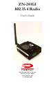
ZN-241GI 802.15.4 Radio User’s Guide 3079 Premiere Pkwy, Ste. 140 Duluth, Georgia 30097 www.cirronet.
Important Regulatory Information Cirronet Product FCC ID: HSW-ZN241 IC 4492A-ZN241 Note: This unit has been tested and found to comply with the limits for a Class A digital device, pursuant to part 15 of the FCC Rules. These limits are designed to provide reasonable protection against harmful interference when the equipment is operated in a commercial environment.
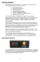
Getting Started The ZN-241G Starter Kit contains all of the items listed below. Before starting, identify each of the items in your kit. o o o o o o o ZN-241GI Radio Unit Reverse polarity antenna Loop-Back Jumper Wall-mount power supply RS-232 Configuration Cable Additional Data/Power Supply connector Software and Manual CD The ZN-241GI radio is a simple-to-use, simple-to-setup wireless networking device.
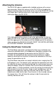
Attaching the Antenna The ZN-241GI radio is supplied with a foldable antenna with a screw type connector. Attach the antenna to the ZN-241GI by threading the antenna onto the antenna connector on the rear of the ZN-241GI, turning until finger tight. Fold the antenna at a right angle so the antenna is sticking up above the ZN-241GI.
Installing the Loop-Back Jumper To run the communications test, it is necessary to install the Loop-Back jumper between pins 5 and 6 on one of the ZN-241GIs. This will send whatever data is transmitted to the ZN-241GI back to the ZN-241G that sent the data. This removes the need to have two PCs to run the test. The Loop-Back connector is just a short piece of wire. Depress the two orange levers below the Data/Power holes corresponding to pins 5 and 6 on the ZN-241GI.
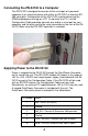
Connecting the ZN-241GI to a Computer The ZN-241GI is designed to connect to the serial port of a personal computer or an industrial device with either an RS-232C or two-wire RS485 serial port. Configuration of the ZN-241GI is performed using the ZNWizard program running on a PC. To connect to a PC, use the Configuration Cable provided, connect one end to a serial port on your computer and the other end to the serial connector on the rear of the ZN241GI. Make sure that RS-232C operation is selected.
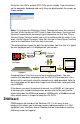
Connect the wall-mount end of the power supply to a wall outlet with either 110VAC or 220VAC. The Power LED on the ZN-241GI will come on and after a moment the Data LED will blink. The Data LED blinking means the ZN-241GI is looking for another ZN-241G to link to. Repeat this step with the other ZN-241GI. After a few seconds, the Link LEDs on both ZN-241Gs will be lit. This indicates that the two ZN-241Gs have established a wireless link.
When you click OK, a window will open up labeled COM1 Properties (or whatever COM port you selected) with a tab labeled Port Settings as shown below. In the Bits per Second window, select 38400. Make sure the other windows show 8, None, 1 and Hardware. Click Apply and then OK. You will now be at a window labeled ZN-241G-Hyper Terminal.
Verify the Link LEDs on both ZN-241Gs are on steady. Type characters on the computer keyboard and verify they are displayed on the screen as shown below. Note: If you press the Enter key, Hyper Terminal will move the cursor to the start of the line but will NOT move it down the screen. Any keys then typed will overwrite the previously typed characters on that line. This is the way Hyper Terminal works and is not a problem with the radio.
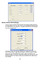
Select Comm Port Settings Click on Connect and the Select Comm Port Settings dialog will display as shown below. The “OK” after COM1 in the dialog below indicates that the COM1 port on the computer is available. Ports that are not available have N/A instead of OK. The Select Comm Port Settings dialog is pre-loaded with settings the ZN-241G has when it ships from the factory. In most instances, simply clicking OK will allow ZNWizard to find the radio and load the main program window.
The first is to use the drop down menus to change the default settings for Comm Port, Baud Rate, Parity and Stop Bits to the correct values. Obviously, this assumes you know which settings the radio is using. If, however, those parameters may have been changed and are not known, a second method is available. The Auto Detect Function The Auto Detect function works this way. If set to FALSE, once OK is selected, the program uses the default settings to try to communicate with the radio.
Configuration Fields The following table is a description of the Configuration Fields grouped into the three sections (Network Settings, Radio Comm Settings and Channel Mask) of the ZNWizard main window. In the center of the dialog window is a box labeled “Network Settings”. The first drop down menu is labeled “Network” as shown below. Network This setting selects the type of network of ZN241Gs you would like to set up.
The four other fields under Network Settings are described below. Device Mode This is how a radio is set to be a Base or a Remote radio when either Point-to-Point or Multipoint mode is selected for the type of network. Only one radio in a network can be the base. Note: If Auto-Config is selected in the Network setting field, ZNWizard will not let you set the radio as a Base or Remote.
The Radio Comm Settings change the serial port settings on the ZN241G. The dialog box that opens when you first start ZNWizard changes the settings for your PC but doesn’t change the radio settings. When you make changes to these settings in the ZN-241G, ZNWizard automatically changes the settings on your PC so you can still talk to the radio. Baud Rate Parity Bit Stop Bits Channel Mask This is the speed that the ZN-241G talks to other devices through its serial port.
Advanced Setup The ZN-241G is a very capable and flexible radio. The features and functions described in this manual, while sufficient for most applications, are only a subset of the complete set. For more advanced applications, please contact Cirronet Tech Support (tech_sup@cirronet.com) for the Technical Reference Manual. Specifications/Hardware Requirements • Star topology w/limited peer-to-peer capability. 1 base, up to 60 remotes.
Warranty Seller warrants solely to Buyer that the goods delivered hereunder shall be free from defects in materials and workmanship, when given normal, proper and intended usage, for twelve (12) months from the date of delivery to Buyer. Seller agrees to repair or replace at its option and without cost to Buyer all defective goods sold hereunder, provided that Buyer has given Seller written notice of such warranty claim within such warranty period.