
User`s guide


Installing the Loop-Back Jumper
To run the communications test, it is necessary to install the Loop-Back
jumper between pins 5 and 6 on one of the ZN-241GIs. This will send
whatever data is transmitted to the ZN-241GI back to the ZN-241G that
sent the data. This removes the need to have two PCs to run the test.
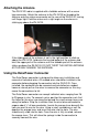
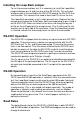
The Loop-Back connector is just a short piece of wire. Depress the two
orange levers below the Data/Power holes corresponding to pins 5 and 6
on the ZN-241GI. When the holes for the wires are along the top, pin 1
will be on the left looking at the orange levers. Pins 5 and 6 are the last
two pins on the right side of the connector. Once the Loop-Back jumper
is inserted, release the two orange levers to secure the connection.
RS-232C Operation
The ZN-241GI is shipped from the factory set up for three-wire RS-232C
operation. Three-wire means a device can communicate with the ZN-
241GI with just Tx, Rx, and Ground connected. Three-wire also means
there is no flow control. Thus the device attached to the ZN-24GI must
be able to receive all the data the ZN-241GI sends to it and the device
must not send data to the ZN-241GI faster than it can be transmitted.
The ZN-241GI was designed to operate in polling environments and can
handle data packets up to 75 bytes in length.
The Tx signal on the ZN-241GI is an output and should be connected to
the RX input of the connected device. The Rx signal on the ZN-241G is
an input and should be connected to the Tx output of the connected
device.
RS-485 Operation
By connecting pins 3 and 4 on the Data/Power connector of the ZN-
241GI, two-wire RS-485 operation is selected. (After the communications
test, the Loop-Back jumper can be used to select 485 mode if desired.)
Two-wire operation means that the ZN-241GI can either be outputting
data on the 485 lines or receiving data on the 485 but not both
simultaneously. This is also called half-duplex operation. This mode of
operation is typically used in polling environments, such as Modbus.
Some master device in the network must insure that only one device is
sending data at any given time. This is what happens naturally in a
polling environment.
Baud Rates
The default baud rate for the ZN-241GI is 38,400 bps in both RS-232C
and RS-485 modes of operation. The ZNWizard program can be used to
change the baud rate.
3