
Owner manual


AN225
2
so that it can continue normal metering operations
once the line power is restored. When the
CS5460A is controlled by a microcontroller, the mi-
crocontroller is typically programmed (by the user)
to handle these power-fail-reset situations. In the
case of auto-boot, the CS5460A may be expected
to reset itself (by re-executing the Auto-Boot se-
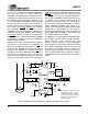
quence) whenever the line-power is restored. Fig-
ure 1 shows a reasonably reliable way to configure
the CS5460A’s RESET
and INT pins of the
CS5460A to restart the Auto-Boot sequence after
a brown-out or black-out condition. This configura-
tion employs a diode, a resistor, and a capacitor on
the RESET
pininanattempttoallowtheCS5460A
to reboot after a sudden loss of power, followed by
a reinstatement of power.
Note that in the above auto-boot example code set
(see Section 1.2) the LSD bit is un-masked, in or-
der to cause a high-to-low transition on the INT
pin
whenever the PFMON low-supply threshold is
reached on the PFMON pin. If a power supply loss
condition is sensed on PFMON, then the INT
pin is
asserted to low (because LSD is un-masked),
which allows the BAT85 diode to quickly drain the
charge on C
BOOT
. But whenever the +5V power is
restored, the resistor-capacitor network will force
RESET
to recharge slowly. The slow rise-time on
the RESET
pin can help to allow the oscillator cir-
cuitry and the CS5460A’s internal reference circuit-
ry enough time to stabilize before the device
attempts to re-execute with the Auto-Boot se-
quence. This will allow the CS5460A to resume its
normal metering operations after power is re-
stored. (User must provide suitable resistor divider
configuration on the PFMON pin, see Figure 1.)
Use of this configuration does not guarantee that
the CS5460A will reset properly, when exposed to
any sudden disturbance in power.
In addition to the configuration described above,
the designer should include sizeable common-
mode capacitors to the VA+/VD+ pins (see
Figure 1). Such capacitance on the analog/digital
power supply pins will increase the amount of time
over which the CS5460A will remain operational
after power is lost, which therefore increases the
chances that the CS5460A will successfully re-ex-
ecute a proper reboot upon restoration of power.
Suggested values are >47 µF (per pin) or >100 µF
(total).
N
L
LOAD
AGND
T2
AG
ND
T1
IIN-
IIN+
VIN-
VIN+
+5V
+5V
VA+ VD+
CS5460A
AGND
VA- DGND
REFOUT
REFIN
00000
TOTALIZER
DGND
SPI
EOUT
EDIR
E
2
PROM
Mode
RESET
INT
10k
30uF
DGND
BAT85
PFMON
AG
N
D
XIN
XOUT
CRYSTAL
4.096 MHz
C
BOOT
47 uF
47 uF
DGND
+
+
+
Figure 1. CS5460A Auto-Boot Configuration: Automatic Restart After Power Failure
This resistor-capacitor- diode
configuration helps to ensure a
smooth power-down, as well as
a proper power-up/reset during
and after a power black-out or
brown-out event.