
User guide

CobraNet Programmer’s Reference
Control Communications
DS651PM25 ©Copyright 2006 Cirrus Logic, Inc. 13
Although the serial bridging feature strives to transmit data at wire speed, delays are
introduced by the process of serializing, de-serializing, and prioritizing the serial bridge
packets. These delays are typically on the order of 10ms or less.
See Table 6.4.8 on page 86 for details on the MI variables used to control serial bridging.
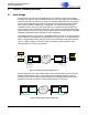
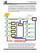
2.2 Packet Bridge
The packet bridge provides a means for using the CobraNet interface as if it were an
Ethernet controller by providing a basic capability to send and receive raw Ethernet
packets. A CobraNet device utilizing a host processor with network stack can use this
feature to transmit and receive both control and audio data over the same network
connection.
In the simplest implementation, the host sees the packet bridge as several control
variables, a receive buffer, and a transmit buffer which are accessed via the HMI interface.
Ethernet data packets are transferred in both directions over the host port using the same
HMI semantics used to read and write other MI variables.
More advanced implementations can take advantage of interrupt and DMA modes of HMI
operation as well as some HMI operations specifically tailored to packet bridge functions.
Refer to Table 6.4.7 on page 81 for details on the MI variables used to control packet
bridging.
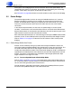
2.2.1 Packet Bridge Buffer Data Format
Packets are transmitted by writing raw packet data to bridgeTxPktBuffer. Packets are
received by reading bridgeRxPktBuffer. Data in both buffers shares the same format. The
first word of the buffer specifies the byte length of the data that follows. Byte length
includes the14-byte Ethernet header. The Frame Check Sequence (FCS) is automatically
appended to transmitted packets and automatically checked and stripped from received
packets. The FCS is not included in the packet data or byte length specification. Byte
length should be in the range 14 to 1514.
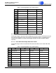
2.2.1.1. Processor-dependent Layout of Packet Bridge Buffers
Refer to Ta bl e 3 and Table 4 on page 14 for organization of data within bridge buffers for
24- and 32-bit platforms. All data marked as unused/0 will be received as 0 and must be
set to 0 when writing the buffer prior to transmission.
For both platforms, requested transmissions shorter than the 60-byte Ethernet packet
minimum will be padded to 60 bytes with indeterminate data.