
Instruction Manual
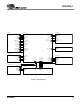
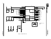
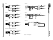
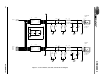
Table Of Contents
- Features
- Description
- 1. General information
- 2. Schematic Description
- 3. Grounding and Layout
- 4. References
- 4.1 ADDENDUM
- Figure 1. Block Diagram
- Figure 2. CS4202 Audio Codec
- Figure 3. Analog Inputs
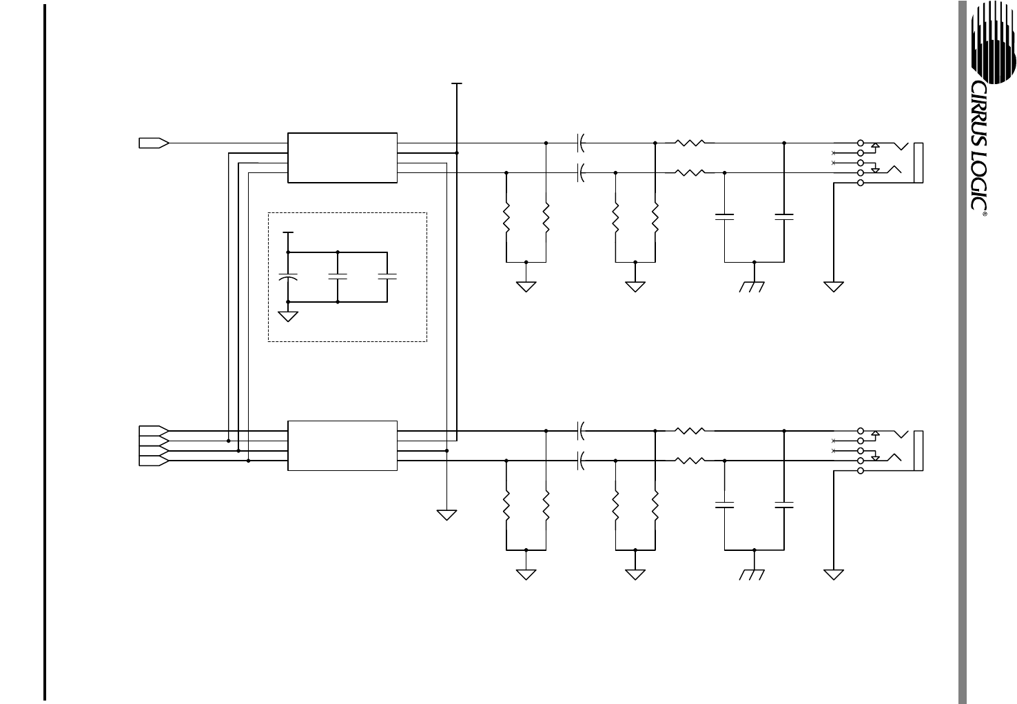
- Figure 4. Center Channel, Surround, and Sub-Woofer Outputs
- Figure 5. Front Channel and Headphone Sense Output
- Figure 6. S/PDIF Optical Output
- Figure 7. CNR Connector
- Figure 8. Phase Locked Loop
- Figure 9. Auto Demotion and Serial Buffers
- Figure 10. PCB Layout: Top Assembly Drawing
- Figure 11. PCB Layout: Top Layer
- Figure 12. PCB Layout: Bottom Layer
- Figure 13. PCB Layout: Drill Drawing
- Figure 14. PCB Layout: Top Silkscreen
- 4.1 ADDENDUM
- 5. bill of materials
CRD4202-1
10 DS549RD1A1
R40
47K
R39
270K
C40
10uF
ELEC
+ C42
0.1uF
Z5U
C41
0.1uF
Z5U
C39
2700pF
X7R
C45
2700pF
X7R
R33
270K
U2 CS4334
SDATA
1
DEM#/SCLK
2
LRCK
3
MCLK
4
AOUTR
5
AGND
6
VA+
7
AOUTL
8
C46
2700pF
X7R
C36 1uF
ELEC
+
C38
2700pF
X7R
J9
4
3
5
2
1
R30 560
R31 560
R36 560
R34
47K
R38
270K
R37 560
R35
47K
J8
4
3
5
2
1
C37 1uF
ELEC
+
C43 1uF
ELEC
+
R32
270K
U3 CS4334
SDATA
1
DEM#/SCLK
2
LRCK
3
MCLK
4
AOUTR
5
AGND
6
VA+
7
AOUTL
8
C44 1uF
ELEC
+
R41
47K
AGND
AGND
AGND AGND
+5VA
CGND
CGND
AGND
AGNDAGND
AGND
+5VA
SCLK
MCLK
LRCLK
SDOUT1
SDOUT0
CNT/LFE
JACK
Connect CGND
to AGND at
the jack
Connect CGND
to AGND at
the jack
SURROUND
JACK
Figure 4. Center Channel, Surround, and Sub-Woofer Outputs