
Instruction Manual
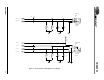
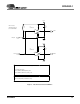
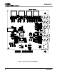
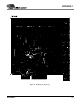
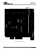
Table Of Contents
- Features
- Description
- 1. General information
- 2. Schematic Description
- 3. Grounding and Layout
- 4. References
- 4.1 ADDENDUM
- Figure 1. Block Diagram
- Figure 2. CS4202 Audio Codec
- Figure 3. Analog Inputs
- Figure 4. Center Channel, Surround, and Sub-Woofer Outputs
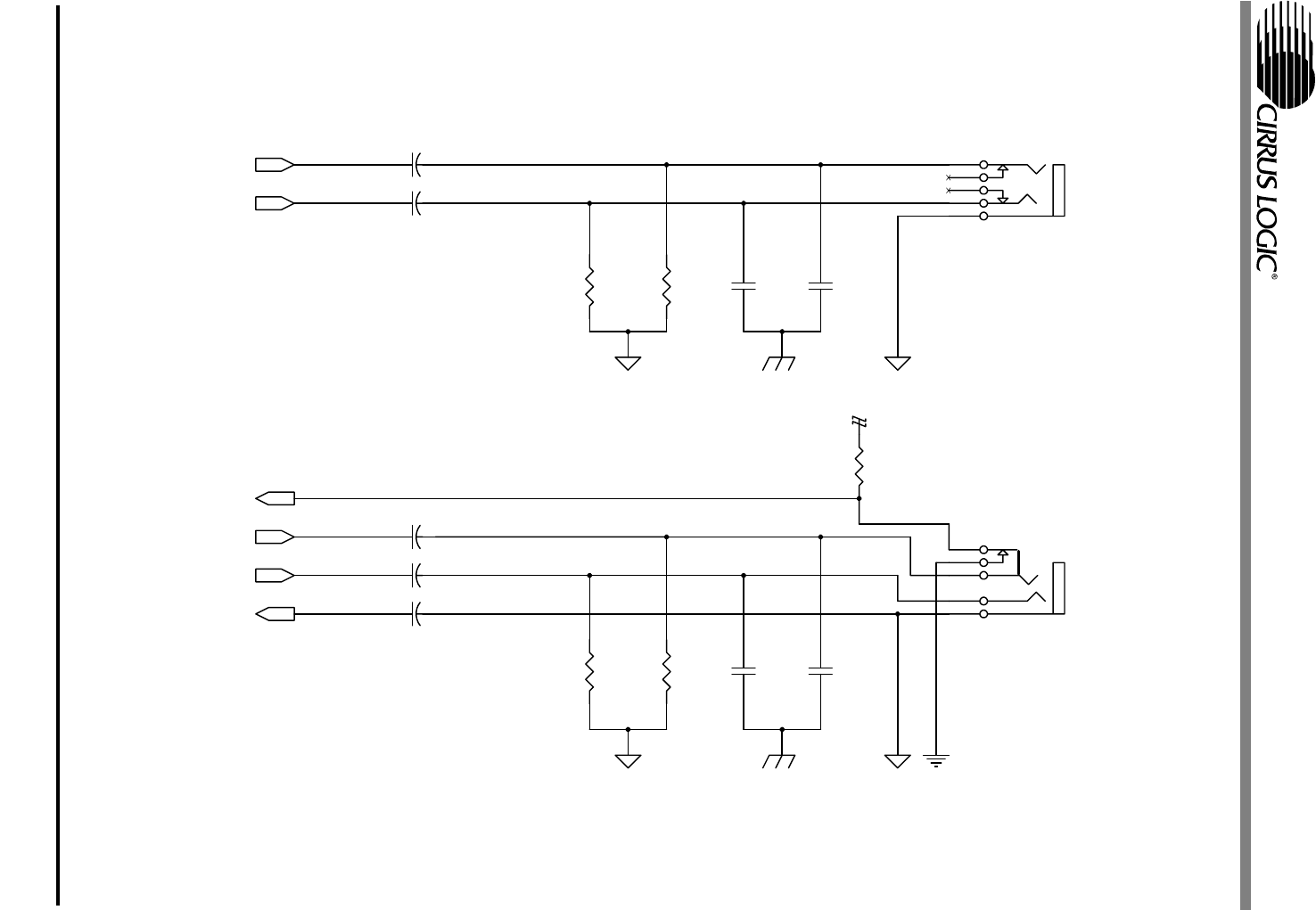
- Figure 5. Front Channel and Headphone Sense Output
- Figure 6. S/PDIF Optical Output
- Figure 7. CNR Connector
- Figure 8. Phase Locked Loop
- Figure 9. Auto Demotion and Serial Buffers
- Figure 10. PCB Layout: Top Assembly Drawing
- Figure 11. PCB Layout: Top Layer
- Figure 12. PCB Layout: Bottom Layer
- Figure 13. PCB Layout: Drill Drawing
- Figure 14. PCB Layout: Top Silkscreen
- 4.1 ADDENDUM
- 5. bill of materials
CRD4202-1
DS549RD1A1 11
C57
100pF
NPO
J11
6
2
3
1
7
R45
220K
C48 1uF
ELEC
+
C56 1uF
ELEC
+
C58
100pF
NPO
R56
10K
R48
10K
C49 1uF
ELEC
+
J10
4
3
5
2
1
C54 220uF
ELEC
+
C50
100pF
NPO
C55 220uF
ELEC
+
R49
10K
C51
100pF
NPO
R44
220K
AGND
CGND
AGND
CGND
AGND
AGND DGND
+3.3VD
GPIO2
HP_OUT_C
LINE_OUT_R
LINE_OUT_L
HP_OUT_R
HP_OUT_L
Connect CGND
to AGND at
the jack
Connect CGND
to AGND at
the jack
LINE OUT
JACK
HEADPHONE
JACK
Figure 5. Front Channel and Headphone Sense Output