
Manual
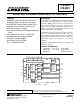

CS4220 CS4221
DS284PP3 3
5.7.1 Master Clock Control (MCK) .................................................................................. 17
6. PIN DESCRIPTIONS — CS4220 ............................................................................................ 18
7. PIN DESCRIPTIONS — CS4221 ............................................................................................ 20
8. APPLICATIONS ..................................................................................................................... 22
8.1 Overview .......................................................................................................................... 22
8.2 Grounding and Power Supply Decoupling ....................................................................... 22
8.3 High Pass Filter ............................................................................................................... 22
8.4 Analog Outputs ................................................................................................................ 22
8.5 Master vs. Slave Mode .................................................................................................... 22
8.6 De-emphasis ................................................................................................................... 22
8.7 Power-up / Reset / Power Down Calibration ................................................................... 22
8.8 Control Port Interface (CS4221 only) .............................................................................. 23
8.8.1 SPI Mode ............................................................................................................ 23
8.8.2 I
2
C Mode ............................................................................................................. 23
8.9 Memory Address Pointer (MAP) ...................................................................................... 24
8.9.1 Auto-Increment Control (INCR) .............................................................................. 24
8.9.2 Register Pointer (MAP) .......................................................................................... 24
9. ADC/DAC FILTER RESPONSE ............................................................................................. 28
10. PARAMETER DEFINITIONS ................................................................................................ 29
11. PACKAGE DIMENSIONS .................................................................................................... 30
LIST OF FIGURES
Figure 1. Serial Audio Port Data I/O Timing .................................................................................. 7
Figure 2. SPI Control Port Timing ................................................................................................. 8
Figure 3. I
2
C Control Port Timing .................................................................................................. 9
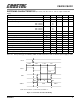
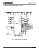
Figure 4. CS4220 Recommended Connection Diagram ............................................................. 10
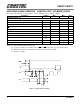
Figure 5. CS4221 Recommended Connection Diagram ............................................................. 11
Figure 6. Control Port Timing, SPI mode .................................................................................... 24
Figure 7. Control Port Timing, I
2
C mode ..................................................................................... 24
Figure 8. Serial Audio Format 0 (I2S) .........................................................................................25
Figure 9. Serial Audio Format 1 .................................................................................................. 25
Figure 10. Serial Audio Format 2 ................................................................................................ 25
Figure 11. Serial Audio Format 3 ................................................................................................ 26
Figure 12. Optional Input Buffer .................................................................................................. 26
Figure 13. Single-ended Input Application .................................................................................. 26
Figure 14. 2- and 3-Pole Butterworth Filters ............................................................................... 27
Figure 15. Hybrid Digital/Analog Attenuation .............................................................................. 27
Figure 16. De-emphasis Curve ................................................................................................... 27
Figure 17. Hybrid Analog/Digital Attenuation .............................................................................. 27
Figure 18. ADC Filter Response ................................................................................................. 28
Figure 19. ADC Passband Ripple ............................................................................................... 28
Figure 20. ADC Transition Band ................................................................................................. 28
Figure 21. DAC Filter Response ................................................................................................. 28
Figure 22. DAC Passband Ripple ............................................................................................... 28
Figure 23. DAC Transition Band ................................................................................................. 28
LIST OF TABLES
Table 1. Example Volume Settings............................................................................................... 15
Table 2. Common Clock Frequencies........................................................................................... 18
Table 3. Digital Interface Format - DIF1 and DIF0....................................................................... 19
Table 4. De-emphasis Control ...................................................................................................... 19
Table 5. Common Clock Frequencies........................................................................................... 20