
User Manual


DS899F1 38
CS4234
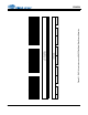
4.6.2 ADC Path
4.6.2.1 Analog Inputs
AINx+ and AINx- are line-level differential analog inputs. The analog input pins do not self-bias and must
be externally biased to VA/2 to avoid clipping of the input signal. The full-scale analog input levels are
scaled according to VA and can be found in the Analog Input Characteristics table.
The ADC output data is in two’s complement binary format. For inputs above positive full scale or below
negative full scale, the ADC will output 7FFFFFH or 800000H, respectively, and cause the ADC Overflow
bit in the Interrupt Notification 1 register to be set to a ‘1’.
When used with the CS44417, whose current monitoring circuitry is single ended, the CS4234’s AINx-
nets should be joined together and connected to the VQ output from the CS44417. This connection will
prevent any variances in the reference voltages of the CS4234 and the CS44417 from skewing the
CS44417 output current measurements. Refer to Figure 2 for more details concerning these connections.
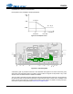
4.6.2.2 ADC HPF
The ADC path has an optional HPF which can be enabled or disabled for all four ADCs via the “ENABLE
HPF” bit in the "ADC Control 1" register. The HPF should only be disabled when the DC component of
the input signal needs to be preserved in the digital output data (i.e. current monitoring with the CS44417).
The HPF characteristics are given in the ADC Digital Filter Characteristics table and plotted in Section 7.
The Analog Input Characteristics table specifies the DC offset error when the HPF is enabled or disabled.
Gain / Volume
AIN4 (±)
AIN3 (±)
AIN2 (±)
AIN1 (±)
Inter polation
Filter
Channel Volume ,
Mute, Invert ,
Noise Gate
Multi-bit
Modulators
AOUT1 (±)
AOUT2 (±)
AOUT3 (±)
AOUT4 (±)
I
2
C Control
Data
Control Port
Level Tr anslator
VL
1 . 8 t o 5.0 VD C
RSTINT
SDIN1SDOUTx
Group
Delay
0-500 uS
Master C l ock In
Fr ame Sync
Clock / LRCK
SDIN 2
Serial C lock
In / Out
LDO Analog Supply
2.5 V
VA
5. 0 VD C
VD
2.5 VD C
Low -Latency
Demux
5
th
DAC
Input Advisory
DAC &
Analog
Filters
Tracking
SMPS
Enable
Sample
& Hold
Mute, Invert ,
Noise Gate
Master
Volum e
Contr ol
Serial Audio Inter face
AOU T 5 (±)
(SM PS C ontr o
DAC &
Anal og
Filters
Master
Vol . Cntr l
Select
Master Volume
0 dB
TPS
GAIN
Filter
Select
X
Inter polation Filter
Sample & Hold
Max
Detect
Envel ope
Tracki ng
Mute, Invert ,
Noise Gate
DAC
Volum e
Multi-bit
Modulators
Mode
Select
Full Scale Code
X
DC Offset
Digital Filters
Multi-bit
ADC
-2
X
Gain
Select
-1
Figure 23. ADC Path