
User Manual


DS899F1 75
CS4234
Signal Color Key:
Signal Coming into the Block
Signal Going out of the Block
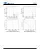
Envelope of Abs.
Max
0V
Mode
Select
Gain / Volu me
Interpo lation
Filt er
Ch . Volume,
Mute, I nvert,
Noise Gate
Mu lti-b i t
Modulators
I
2
C Cont rol
Da ta
Co nt ro l Por t
Le vel Tr an slator
VL
1. 8 to 5.0 VDC
RSTINT
SDIN1SDOUTx
Group
Delay
0-500uS
Master Clock In
Frame Sync
Clock / LR C K
SDIN2
Serial Clock
In / O ut
LDO Anal og Su pp ly
2.5 V
VA
5.0 VD C
VD
2. 5 V DC
Low-Latency
Demux
5
th
DAC
Input Advisory
DAC &
Analog
Filters
Tracking
SMPS
Enable
Sample
& Ho ld
Mute , In vert,
Noise Gate
Master
Volume
Cont rol
S er ial Au di o Int erface
DA C &
Analog
Filters
Ma st er
Vol. Cntrl
Select
Master Volume
0 dB
TPS
GAIN
Filter
Select
X
I nte rp ola tion Filte r
Sample & Ho l d
Ma x
Detect
Enve l ope
Tracking
Mute , In vert,
Noise Gate
DAC
Volume
Multi-bit
Modulators
Supply Rails
Voltage
&
Current Gain
Swi tch mode Power Supply
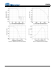
Ful l S c ale Code
-2
X
X
DC Off set
K1
K5
K2
Configured to be Referenced
to Full Scale by setting TPS
Mode Register to “1”
Abs. Max
0V
Ch. 2
Ch. 3
Ch. 4
Ch. n
.
.
.
.
Ch. 1
Signals Coming into the Tracking Engine
0V
0V
0V
0V
K3
K4
Envelope of Abs. Max with
Gai n and DC Offset Applied
via TPS OFFSET Regi ster
Ga i n
Se lect
-1
AIN4 (±)
AIN3 (±)
AIN2 (±)
AIN1 (±)
Digital Filters
Multi-bit
ADC
for simplicity only
Ch. 1 is tracked
0V
0V
0V
Full Scale
-2 gain
-1 gain
Envelope of Abs. Max with
Gain Applied via DAC5
Volume Control Register
Figure 47. Progression of the Tracking Signal Through the DAC5 Path