
User Manual


DS605F2 33
CS42428
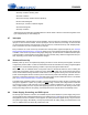
4.5.4.3 OLM Config #3
This configuration will support up to 8 channels of DAC data and 6 channels of ADC data. OLM Config #3
will handle up to 20-bit ADC samples at an Fs of 48 kHz and 24-bit DAC samples at an Fs of 48 kHz. Since
the ADC’s data stream is configured to use the ADC_SDOUT output and the internal and external ADCs
are clocked from the ADC_SP, the sample rate for the DAC Serial Port can be different from the sample
rate of the ADC serial port.
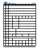
Register / Bit Settings Description
Functional Mode Register (addr = 03h)
Set DAC_FMx = 00,01,10
DAC_LRCK can run at SSM, DSM, or QSM independent of ADC_LRCK
Set ADC_FMx = 00,01,10
ADC_LRCK can run at SSM, DSM, or QSM independent of DAC_LRCK
Set ADC_CLK_SEL = 1
Configure ADC_SDOUT to be clocked from the ADC_SP clocks.
Interface Format Register (addr = 04h)
Set DIFx bits to proper serial format
Select the digital interface format when not in One-Line Mode
Set ADC_OLx bits = 00,01
Select ADC operating mode, see table below for valid combinations
Set DAC_OLx bits = 00,01,10
Select DAC operating mode, see table below for valid combinations
Misc. Control Register (addr = 05h)
Set DAC_SP M/S = 1
Set DAC Serial Port to Master Mode.
Set ADC_SP M/S = 0 or 1
Set ADC Serial Port to Master Mode or Slave Mode.
Set EXT ADC SCLK = 0
Identify external ADC clock source as ADC Serial Port.
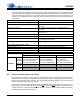
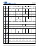
DAC Mode
Not One-Line Mode One-Line Mode #1 One-Line Mode #2
ADC Mode
Not One-
Line Mode
DAC_SCLK=64Fs
DAC_LRCK=SSM/DSM/QSM
ADC_SCLK=64Fs
ADC_LRCK=SSM/DSM/QSM
DAC_SCLK=128Fs
DAC_LRCK=SSM/DSM
ADC_SCLK=64Fs
ADC_LRCK=SSM/DSM/QSM
DAC_SCLK=256Fs
DAC_LRCK=SSM
ADC_SCLK=64Fs
ADC_LRCK=SSM/DSM/QSM
One-Line
Mode #1
DAC_SCLK=64Fs
DAC_LRCK=SSM/DSM/QSM
ADC_SCLK=128Fs
ADC_LRCK=SSM
DAC_SCLK=128Fs
DAC_LRCK=SSM/DSM
ADC_SCLK=128Fs
ADC_LRCK=SSM
DAC_SCLK=256Fs
DAC_LRCK=SSM
ADC_SCLK=128Fs
ADC_LRCK=SSM
One-Line
Mode #2
not valid not valid not valid
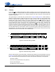
SCLK_PORT1
LRCK_PORT1
SDIN_PORT1
SCLK_PORT2
LRCK_PORT2
SDOUT1_PORT2
SDOUT2_PORT2
SDOUT3_PORT2
SDOUT4_PORT2
RMCK
ADCIN1
ADCIN2
MCLK
SDOUT1
SDOUT2
LRCK
SCLK
64Fs,128Fs
DIGITAL AUDIO
PROCESSOR
CS5361
CS5361
ADC_SCLK
ADC_LRCK
ADC_SDOUT
DAC_SCLK
DAC_LRCK
DAC_SDIN1
DAC_SDIN2
DAC_SDIN3
DAC_SDIN4
MCLK
64Fs,128Fs,256Fs
Figure 19. OLM Configuration #3
CS42426