
Instruction Manual

44 DS632F1
CS44800
5.1.4 Recommended Power-Down Sequence
1. Mute all channel outputs by setting the corresponding CHxx_MUTE bits to ‘1’b.
2. When driving a single-ended (half-bridged) power output stage, set the RAMP[1:0] bits to ‘01’b and the required ramp speed, to initiate
a ramp cycle when the channel is powered down.
3. Power down each channel’s PWM modulator by setting the PDN_PWMxx bit to ‘1’b. If single-ended, this will initiate a sequence which
will slowly decrease the DC voltage, from Vpower÷2 to 0 V, across the AC-coupling capacitor.
4. The ramp-down function can be configured to cause an interrupt condition when the ramp period has completed. This will be indicated
by an active INT
signal.
5. Once the ramp-down sequence has completed, set the appropriate GPIO pin, or other control signal, to power down the power output
stage.
6. For full-bridged power output stage configurations, the ramp-down sequence is not required. Powering down the power output stage
will not cause an audible pop from the speaker.
7. Concurrently with the ramp-down sequence, if desired, stop all clocks on the DAI interface (DAI_MCLK, DAI_SCLK, DAI_LRCK).
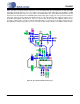
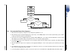
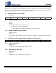
Set PSR_EN = 1b
Set PSR_EN = 0b
Read DEC_OUTD[23:0]
3FEF90h <
DEC_OUTD[23:0] <
400FFFh?
Done
DEC_OUTD[23:0] >
400FFFh?
YN
C
PSR
=C
PSR
- 9Bh
Set PSR_RESET = 1b
C
PSR
=C
PSR
+ 9Bh
YN
Figure 30. PSR Calibration Sequence