
User`s manual


3-1 Copyright 2009 Cirrus Logic, Inc. DS734UM7
Introduction
CS485xx Hardware User’s Manual
Chapter 3
Serial Control Port
3.1 Introduction
The CS485xx uses the Serial Control Port (SCP) to communicate with external devices such as host
microprocessors using either I
2
C or SPI serial communication formats. The port can be configured as either
a master or slave. The CS485xx DSP serial port communicates using the SCP_CLK, SCP_MOSI,
SCP_MISO (SPI serial master and slave modes), and SCP_SDA (for I
2
C
serial master and slave modes)
pins.
In both SPI and I
2
C modes, the serial control port performs 8-bit transfers and is always configured as a
slave for external device-controlled data transfers. As a slave, it cannot drive the clock signal nor initiate data
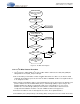
transfers. The port can request a read from the host by dropping the SCP_IRQ
pin. The port can also
indicate that the host should stop sending data by dropping the SCP_BSY
pin.
Note: The host must obey the SCP_BSY
pin status. Messages sent to the DSP’s serial control port
(SCP) when SCP_BSY
pin is low will be lost.
The CS485xx SPI and I
2
C serial communication modes are identical from a functional standpoint. The main
difference between the two is the actual protocol being implemented between the CS485xx and the host. In
addition, the I
2
C slave has a true I
2
C mode that utilizes data flow mechanisms inherent to the I
2
C protocol. If
this mode is enabled, the I
2
C slave will hold SCP_CLK low to delay a transfer as needed -- this is in addition
to activating SCP_BSY
.
3.2 Serial Control Port Configuration
The serial control port configuration for an operating mode is determined by the state of hardware boot
select pins as the CS485xx exits reset. The rising edge of the RESET
pin samples the HS[4:0] pins to
determine the communication mode and boot style. The CS485xx O/S currently supports two serial control
port configurations for host control:
•I
2
C Slave (Write Address = 0x80, Read Address = 0x81)
• SPI Slave (Write Address = 0x80, Read Address = 0x81)
The HS[4:0] signals latched by RESET
are read by the boot ROM code to determine the format (SPI slave or
I
2
C slave). If a slave mode is chosen, the ROM code then configures the serial control port for slave mode
and looks for the BOOT_START message. If a master mode is chosen, the ROM code starts fetching code
from address 0x00. Please see Chapter 2, "Operational Modes" for additional details on configuring
CS485xx ports and communication modes.
Procedures for configuring the serial control port for SPI and I
2
C communication modes are provided in this
section.