
User`s manual


3-3 Copyright 2009 Cirrus Logic, Inc. DS734UM7
Serial Control Port Configuration
CS485xx Hardware User’s Manual
3.2.2 I
2
C System Bus Description
Devices can be considered masters or slaves when performing data transfers. A master is the device which
initiates a data transfer on the bus and generates the clock signals to permit that transfer. Any device
addressed by the initiator is considered a slave.
The I
2
C-bus is a multi-master bus. This means that more than one device capable of controlling the bus can
be connected to it. The master-slave relationships found on the I
2
C bus are not permanent and only depend
on the direction of data transfer at that time. Generation of clock signals on the I
2
C bus is always the
responsibility of master devices; each master generates its own clock signals when transferring data on the
bus. Bus clock signals from a master can only be altered when they are stretched by a slow slave device
holding down SCP_CLK.
Both SCP_SDA and SCP_CLK are bidirectional lines. When the bus is free, both lines are pulled high by
resistors. The output stages of devices connected to the bus must have an open-drain or open-collector to
perform the wired-AND function.
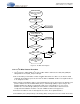
Figure 3-2. Block Diagram of I
2
C System Bus
Table 3-1 shows the signal names, descriptions, and pin number of the signals associated with the I
2
C Serial
Control Port on the CS485xx.
MASTER
ONLY
System Microcontroller
SCP_CLK
SCP_SDA
SCP_IRQ
SCP_BSY
CS485xx
3.3k 3.3k
3.3V
3.3k3.3k
Serial FLASH
SCP_CLK
SCP_SDA
3.3k 3.3k
3.3V
CS485xx
GPIO
CLK
SDA
GPIO
GPIO
RESET
CLK
SDA
SLAVE
ONLY