
User`s manual


Serial Control Port Configuration
CS485xx Hardware User’s Manual
DS734UM7 Copyright 2009 Cirrus Logic, Inc. 3-4
3.2.2.1 I
2
C Bus Dynamics
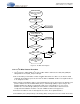
The Start condition for an I
2
C transaction is defined as the first falling edge on the SCP_SDA line while
SCP_CLK is high. An I
2
C Stop condition is defined as the first rising edge on the SCP_SDA line while
SCP_CLK is high. Hence for valid data transfer, SCP_SDA must remain stable during the high period of the
clock pulse. Start and Stop conditions are always generated by the master. The bus is considered to be busy
after the Start condition. The bus is considered to be free again following the Stop condition. The bus stays
busy if a repeated Start condition is generated instead of a Stop condition. In this respect, the Start and
repeated Start conditions are functionally identical.
Figure 3-3. I
2
C Start and Stop Conditions
Table 3-1. Serial Control Port 1 I2C Signals
Pin Name Pin Description
LQFP-48
Pin #
Pin
Type
SCP_CLK
I
2
C Control Port Bit Clock.
In master mode, this pin serves as the serial control clock output
(open drain in I
2
C mode / output in SPI mode). In serial slave
mode, this pin serves as the serial control clock input. In I
2
C
slave mode the clock can be pulled low by the port to stall the
master.
36
Open
Drain
SCP_SDA
Bidirectional Data I
2
C Mode Master/Slave Data IO. In I
2
C
master and slave mode, this open drain pin serves as the data
input and output.
35
Open
Drain
SCP_IRQ
Control Port Data Ready Interrupt Request, Output, Active Low
This pin is driven low when the DSP has a message for the host
to read. The pin will go high when the host has read the
message and the DSP has no further messages.
39
Open
Drain
SCP_BSY
Serial Control Port Input Busy, Output, Active Low
This pin is driven low when the control port’s receive buffer is
full. Internal Buffer is 4 bytes (1 DSP Word) deep.
41
Open
Drain
SCP_CLK
S
CP_SDA
Start
SCP_CLK
S
CP_SDA
Stop