
User`s manual


3-7 Copyright 2009 Cirrus Logic, Inc. DS734UM7
Serial Control Port Configuration
CS485xx Hardware User’s Manual
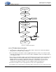
Figure 3-7. Repeated Start Condition with ACK and NACK
3.2.2.2 I
2
C Messaging
Messaging to the CS485xx using the I
2
C bus requires usage of all the information provided in the above I
2
C
Section 3.2.2 “I
2
C System Bus Description” on page 3-3 and Section 3.2.2.1 “I
2
C Bus Dynamics” on page
3-4. Every I
2
C transaction to the CS485xx will involve 4-byte words - for control and application image
download. A detailed description of the serial SPI communication mode is provided in this section. This
includes:
• A flow diagram and description for a serial I
2
C write
• A flow diagram and description for a serial I
2
C read
3.2.2.2.1 SCP_BSY Behavior
The SCP_BSY signal is not part of the I
2
C protocol, but it is provided so that the slave can signal to the
master that it cannot receive any more data. It performs the same function as that of holding SCP_CLK low
to halt transmission. A falling edge of the SCP_BSY
signal indicates the master must halt transmission.
Once the SCP_BSY
signal goes high, the suspended transaction may continue. It is important for the host to
obey the SCP_BSY
pin status for proper communication with the DSP.
3.2.2.3 Performing a Serial I
2
C Write
Information provided in this section is intended as a functional description indicating how to use the
configured serial control port to perform a I
2
C write from an external device (master) to the CS485xx DSP
(slave). The system designer must ensure that all timing constraints of the I
2
C write cycle are met (see the
CS485xx datasheet for timing specifications). When writing to the CS485xx, the same protocol described in
this section will be used when writing single-word messages to the boot firmware, writing multiple-word
overlay images to the boot firmware, and writing multiple-word messages to application firmware. The
examples given can therefor be expanded to fit any I
2
C writing situation.
The flow diagram shown in Figure 3-8 below, illustrates the sequence of events that define the I
2
C write
protocol for SCP. This protocol is discussed in the high-level procedure in Section 3.2.2.3.1.
SCP_CLK
SCP_SDA
Data Byte
ACK
Start
A[6] A[5] A[4] A[3] A[2] A[1] A[0] R/W
ACK
M S M S
W
rite
S M M S
R
ead
SCP_CLK
SCP_SDA
Data Byte
NACK
Start
A[6] A[5] A[4] A[3] A[2] A[1] A[0] R/W
ACK
M S M S
W
rite
S M M S
R
ead
M = Master Drives SDA
S = Slave Drives SDA