
Manual


CS5464
DS682F3 35
E3MODE[1:0] E3 Output Mode (with E1MODE enabled)
00 = Power Fail Monitor
01 = Energy Sign
10 = not used
11 = not used
POS Positive Energy Only. Suppresses negative values in
P1
AVG
and P2
AVG
. If a negative value is
calculated, zero will be stored instead.
AFC Enables automatic line frequency measurement which sets
Epsilon every time a new line fre-
quency measurement completes.
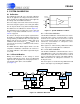
Epsilon is used to control the gain of the 90 degree phase
shift integrator used in quadrature power calculations.
8.3.6 Line to Sample Frequency Ratio (Epsilon) – Address: 17
Default = 0.0125 (4.0 kHz x 0.0125 or 50 Hz)
Epsilon is the ratio of the input line frequency to the output word rate (OWR). It can either be written by the ap-
plication program or calculated automatically from the line frequency (from the voltage input) using the AFC bit
in the
Modes register. It is a two's complement value in the range of -1.0 value 1.0, with the binary point to
the right of the MSB. Negative values are not used.
8.3.7 Pulse Output Width (PulseWidth) – Address: 14
Default = 1 (250 uS at OWR = 4 kHz)
PulseWidth sets the duration of energy pulses. The actual pulse duration is the contents of PulseWidth divided
by the output word rate (OWR).
PulseWidth is an integer in the range of 1 to 8,388,607.
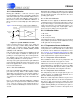
8.3.8 Pulse Output Rate (PulseRate) – Address: 15
Default= -1
PulseRate sets the full-scale frequency for E1, E2, E3 pulse outputs. For a 4 kHz sample rate, the maximum
pulse rate is 2 kHz. This is a two's complement value in the range of -1
value 1, with the binary point to the
left of the MSB.
Refer to 6.10
Energy Pulse Rate on page 20 for more information.
MSB LSB
-(2
0
)2
-1
2
-2
2
-3
2
-4
2
-5
2
-6
2
-7
.....
2
-17
2
-18
2
-19
2
-20
2
-21
2
-22
2
-23
MSB LSB
0
2
22
2
21
2
20
2
19
2
18
2
17
2
16
.....
2
6
2
5
2
4
2
3
2
2
2
1
2
0
MSB LSB
-(2
0
)2
-1
2
-2
2
-3
2
-4
2
-5
2
-6
2
-7
.....
2
-17
2
-18
2
-19
2
-20
2
-21
2
-22
2
-23