
Manual

8 DS641F6
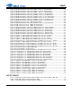
CS8421
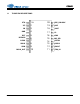
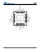
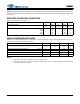
Pin Name # Pin Description
VD 1 Digital Power (Input) - Digital core power supply. Typically +2.5 V.
GND 2 Ground (Input) - Ground for I/O and core logic.
RST
3
Reset (Input) - When RST
is low, the CS8421 enters a low-power mode and all internal states are
reset. On initial power-up, RST
must be held low until the power supply is stable and all input clocks
are stable in frequency and phase.
BYPASS 4
Sample Rate Converter Bypass (Input) - When BYPASS is high, the sample-rate converter will be
bypassed, and any data input through the serial audio input port will be directly output on the serial
audio output port. When BYPASS is low, the sample rate converter will operate normally.
ILRCK 5
Serial Audio Input Left/Right Clock (Input/Output) - Word-rate clock for the audio data on the
SDIN pin.
ISCLK 6 Serial Audio Bit Clock (Input/Output) - Serial-bit clock for audio data on the SDIN pin.
SDIN 7 Serial Audio Input Data Port (Input) - Audio data serial input pin.
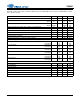
MCLK_OUT 8
Master Clock Output (Output) - Buffered and level-shifted output for Master clock. If MCLK_OUT
is not required, this pin should be pulled high through a 47 k resistor to turn the output off. See
“Master Clock” on page 20.
TDM_IN 9
Serial Audio TDM Input (Input) - Time Division Multiplexing serial audio data input. Grounded
when not used. See “Time Division Multiplexing (TDM) Mode” on page 21.
SDOUT 10
Serial Audio Output Data Port (Output) - Audio data serial output pin. Optionally, this pin may be
pulled low through a 47-k resistor, but must not be pulled high.
OSCLK 11 Serial Audio Bit Clock (Input/Output) - Serial bit clock for audio data on the SDOUT pin.
OLRCK 12
Serial Audio Input Left/Right Clock (Input/Output) - Word rate clock for the audio data on the
SDOUT pin.
MS_SEL 13
Master/Slave Select (Input) - Used to select Master or Slave for the input and output serial audio
ports at startup and reset. See Table 1 on page 18 for settings.
GND 14 Ground (Input) - Ground for I/O and core logic.
VL 15 Logic Power (Input) - Input/Output power supply. Typically +3.3 V or +5.0 V.
SAOF 16
Serial Audio Output Format Select (Input) - Used to select the serial audio output format at
startup and reset. See Table 3 on page 18 for format settings.
SAIF 17
Serial Audio Input Format Select (Input) - Used to select the serial audio input format at startup
and reset. See Table 2 on page 18 for format settings.
SRC_UNLOCK 18
SRC Unlock Indicator (Output) - Indicates when the SRC is unlocked. See “SRC Locking and
Varispeed” on page 19.
XTO 19 Crystal Out (Output) - Crystal output for Master clock. See “Master Clock” on page 20.
XTI 20
Crystal/Oscillator In (Input) - Crystal or digital clock input for Master clock. See “Master Clock” on
page 20.
Thermal Pad -
Thermal Pad - Thermal relief pad for optimized heat dissipation. This pad must be electrically
connected to GND. See “Power Supply, Grounding, and PCB Layout” on page 23 for more
information.