
User Manual


4-12 EP7309/11/12 User’s Manual - DS508UM4
Copyright Cirrus Logic, Inc. 2003
Interrupt Controller
4
URXINT2: UART2 receive FIFO half full interrupt. The function of this
interrup t s ource depends on whether the UART2 FIFO i s enabled.
If the FIFO is disabled, this interrupt will be active when there is
valid RX data in the UART2 RX data holding register and be
cleared by reading this data. If the FIFO is enabled, this interrupt
will be active when the UART2 RX FIFO is half or more full or if
the FIFO i s non-emp ty, and no more characters have been received
for a three-character time-out period, it is cleared by reading all
the data from the RX FIFO. The FIFO is 16 bytes deep.
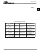
Interrupt Mask Register 2 (INTMR2)
Address: 0x8000.1280, Read / Write
Definition: This register is an extension of INTMR1, containing the interrupt
mask bits. A ll of the interrupts represented in INTMR 2 trigger the
standard interru pt (IRQ) signal of the ARM7 20T core. Please refer to
INTSR2 for individual bit details.
Descriptions:
(See “Interrupt Status Register 2 (INTSR2)” for details)
Interrupt Status Register 3 (INTSR3)
Address: 0x8000.2240, Read / Write
Definition: This register is an extension of INTSR1 and INTSR2 containing only
the status bit for the DAI interface of the EP73xx. Each bit is set if the
appropriate interrupt is active. T he interrupt assignment is given
below.
Bit Descriptions:
RSVD: Unknown during Read.
DAIINT: DA I i nterface interrupt. The cause must be determined by reading
the DAI status register. It is mapped to the FIQ interrupt on the
ARM720T processor
31 30 29 28 27 26 25 24 23 22 21 20 19 18 17 16
RSVD
15 14 13 12 11 10 9 8 7 6 5 4 3 2 1 0
RSVD URXINT2 UTXINT2 RSVD SS2TX SS2RX KBDINT
31 30 29 28 27 26 25 24 23 22 21 20 19 18 17 16
RSVD
15 14 13 12 11 10 9 8 7 6 5 4 3 2 1 0
RSVD DAIINT