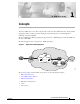
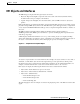
C H A P T E R 1 Concepts The Cisco 10000 series router offers a single solution for leased–line, ATM, frame relay, and broadband aggregation while providing customers with high–performance IP services, maximum platform scalability, and high availability. The Cisco 10000 Series Manager application supports the Cisco 10005 Edge Services Router (ESR) and the Cisco 10008 ESR. The following figure shows a typical Cisco 10000 deployment.
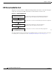
Chapter 1 Concepts EM Documentation Set EM Documentation Set This guide is one part of the Cisco 10000 Series Manager EM documentation set. The following figure displays all of the guides in the EM documentation set and details the contents of each. EM Documentation Set Cisco Element Management Framework Installation and Administration Guide (Release 3.2) Cisco Element Management Framework User Guide (Version 3.2) Cisco 10000 Series Manager Installation Guide (Release 1.
Chapter 1 Concepts Cisco EMF Software Features Cisco EMF Software Features Cisco EMF provides a flexible framework which supports a variety of EMs, making it possible to manage multiple device types within a given network on a single system. Common network management functionality provides for complete management of the logical and physical components of the network. Using a solid base, Cisco EMF provides vital core functionality which allows for optimal network management when combined with EMs.
Chapter 1 Concepts EM Software Features EM Software Features Installed with Cisco EMF, the EM allows for precise management of the device(s) it supports through custom GUI windows and modeling behavior. Invoked from the Cisco EMF Map Viewer application, the EM provides Fault, Configuration, Accounting, Performance, and Security (FCAPS) windows on chassis, module, interface, and connection levels as applicable.
Chapter 1 Concepts EM Objects and Interfaces EM Objects and Interfaces The EM manages both physical and logical objects as follows: • Physical—Represents tangible components and devices such as the chassis (hardware frame), module interfaces and port adapters, and interfaces • Logical—Represents intangible, more abstract features, such as ATM connections objects and profiles Fault, Configuration, Accounting, Performance, and Security (FCAPS) windows are accessible on both physical and logical EM objec
Chapter 1 Concepts EM Objects and Interfaces Figure 1-4 Note Sample Chassis Showing Telecom Graphical Objects For additional information regarding the type of TGO objects that can appear in the EM, see the Cisco Element Management Framework User Guide.
Chapter 1 Concepts EM Objects and Interfaces Physical Objects The following table lists all physical objects created in the EM and the management functions that can be performed on each object. Table 1-1 Physical Objects and Management Functions Physical Object Management Functions Chassis—The hardware frame of the Cisco , which houses all subchassis objects (modules) Fault Configuration Accounting Processor Cards—The Cisco support router processor cards.
Chapter 1 Concepts EM Objects and Interfaces Cisco 10000 Router Chassis The Cisco 10000 Series Manager supports the Cisco 10005 Edge Services Routers (ESR) and Cisco 10008 ESR. The supported Cisco 10000 series routers include a performance routing engine (PRE), a point–to–point passive and redundant backplane, and redundant interface cards. With redundant PREs, power supplies, and fans, the router is protected against any single–point of failure.
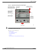
Chapter 1 Concepts EM Objects and Interfaces Figure 1-6 Cisco 10008 Chassis The Cisco 10008 ESR chassis contains ten slots overall. Two centrally located slots accommodate PRE cards and eight slots accommodate line cards, four on either side of the PRE slots. Area for dual PEMs provide redundant power supplies. The blower, located at the top of the chassis’ front view, allows for front–to–back airflow to cool the device.
Chapter 1 Concepts EM Objects and Interfaces Modules The EM supports the following types of modules: • Processor—For a complete listing of the processor modules supported, see Table 1-2. • Generic—For a complete listing of the Generic module interfaces and port adapters the EM supports see Table 1-3. • ATM (Asynchronous Transfer Mode)—For a complete listing of the ATM modules the EM supports see Table 1-4.
Chapter 1 Concepts EM Objects and Interfaces Physical Interfaces and Logical Interface Technologies Physical interfaces and logical interface technologies are modeled as objects below a parent module. As mentioned before, the type of module characterizes the type of interface. Interface types further break down into two categories, physical interfaces and logical interface technologies. Physical interfaces are the ports which exist on line cards.
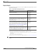
Chapter 1 Concepts EM Objects and Interfaces Interface Type Physical and Logical Interface Technologies SONET SONET Status Performance ATM Fault Configuration Status Performance Profile IP Configuration POS Configuration Profile DS1 E1 Configuration DS3 E3 Configuration Status Performance FCAPS Service Windows Although not technology–specific, physical or logical, generic support is available through Configuration, Status, and Performance windows for each of the interface types in the p
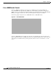
Chapter 1 Concepts Views Views Views are accessible by clicking the Viewer icon on the Cisco EMF launchpad. These views appear in the frame at the left of the window when you open the Map Viewer window (see the following figure for an example). Views model hierarchical relationships between objects, both physical and logical. Objects are organized into different views and can exist in multiple views simultaneously by reference. Each object can have a number of parent and child objects.
Chapter 1 Concepts Views You may or may not see all of these views using this EM (exceptions noted). These views all exist within EMs, however they are not all implemented. If multiple EMs are co–resident, the applicable views are displayed. As the following sections detail, the views you will use to perform the majority of the EM capabilities are the Physical and Component Managed views. Both are similar in structure and allow you to initiate the EM windows.
Chapter 1 Concepts Views Cisco 10000 Series Manager does not support ATM connection management, therefore logical ATM connection objects associated with the supported devices are not apparent in the Component Managed view.
Chapter 1 Concepts Views Figure 1-9 Physical View Chassis Map RME View All objects managed by the RME server display beneath the RME view. Objects are organized by RME server objects. Self Management View This view allows you to monitor network elements which are part of the Cisco EMF system. The Self Management view is non–propagating.
Chapter 1 Concepts Object States Object States Object states reflect the life cycle of an object. Whatever stage the object is in at any given time displays in the state type. The state of an object can change frequently, depending upon what actions take place on the object. All objects within the EM are in a specific state which appears at the bottom left corner of each FCAPS window. The following figure highlights an object’s state.
Chapter 1 Concepts Object States Decommissioned State The decommissioned state indicates that an object is not managed. When you manually deploy an object, the object is normally put into the decommissioned state. Tip Manually deployed objects are initially decomissioned so you have the option of managing the object. If you want to manage the object, you must first commission the object.
Chapter 1 Concepts Object States Lost Comms The lost comms (lost communications) state indicates that the object is not responding to heartbeat polling. The EM can apply this state to a chassis, module, or interface. When an object is in the lost comms state, heartbeat polling occurs on the object. When the object responds to heartbeat polling, it moves out of the lost comms state. For example, say an ATM module in the EM was predeployed.
Chapter 1 Concepts Object States the chassis enters the mismatched state. To rectify this problem, you must either delete the predeployed chassis and deploy the correct one, or fix the IP address by re–entering the correct one in the chassis Management Information window. Preprovisioned Module preprovisioning is available within the EM and device. Module preprovisioning essentially serves as a way to establish place holders for anticipated or expected hardware modules.