
Quick Start Guide


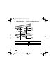

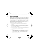
Table Of Contents
- Cisco One-Year Limited Hardware Warranty Terms
- Preface
- Introduction to the Access Point
- Unpacking the Access Point
- Installing the Access Point
- In Case of Difficulty
- Mounting Instructions
- Safety Information
- Compliance Information

FINAL DRAFT - CISCO CONFIDENTIAL
30
3. Slide the access point’s mounting pins into the small ends of the
keyhole-shaped holes on the mounting bracket and apply a slight force
on the I/O panel end. You will hear a click when the locking detent
contacts the access point and locks it into place.
4. Attach and adjust the antenna(s).
5. Connect the Ethernet cable to the access point’s Ethernet port.
6. Insert the 48VDC power output connector into the access point’s local
power plug (if you are using a local power source).
Securing the Access Point to the Mounting
Bracket
The security hasp on the mounting bracket locks the access point to the
bracket to make it more secure. When the access point is properly installed
on the mounting bracket, the holes in the security hasps line up so you can
install a padlock.
Note Known compatible padlocks are Master Lock models 120T or 121T.
12KDBQSG.bk Page 30 Friday, June 21, 2002 9:53 AM