
Installation Guide


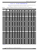
Table Of Contents
- Cisco Aironet 1240AG Series Access Point Hardware Installation Guide
- Contents
- Preface
- Overview
- Installing the Access Point
- Safety Information
- Warnings
- Unpacking the Access Point
- Basic Installation Guidelines
- Before Beginning the Installation
- Installation Summary
- Mounting Overview
- Mounting on a Horizontal or Vertical Surface
- Mounting Below a Suspended Ceiling
- Mounting Above a Suspended Ceiling
- Mounting Access Point on a Desktop or Shelf
- Connecting the Ethernet and Power Cables
- Powering Up the Access Point
- Cable Security Bracket
- Attaching the Access Point to the Mounting Plate
- Securing the Access Point
- Securing the Access Point to the Mounting Plate
- Configuring the Access Point for the First Time
- Using the Web-Browser Interface
- Using the Command-Line Interface
- Troubleshooting
- Translated Safety Warnings
- Declarations of Conformity and Regulatory Information
- Manufacturers Federal Communication Commission Declaration of Conformity Statement
- Department of Communications—Canada
- European Community, Switzerland, Norway, Iceland, and Liechtenstein
- Declaration of Conformity for RF Exposure
- Guidelines for Operating Cisco Aironet Access Points in Japan
- Declaration of Conformity Statements
- Declaration of Conformity Statements for European Union Countries
- Access Point Specifications
- Channels and Power Levels
- Console Cable Pinouts
- Glossary
- Index

Draft 1A - CISCO CONFIDENTIAL
D-3
Cisco Aironet 1240AG Series Access Point Hardware Installation Guide
OL-7293-01
Appendix D Channels and Power Levels
Channels and Maximum Power Levels
IEEE 802.11a (5-GHz Band)
An improper combination of power level and antenna gain can result in equivalent isotropic radiated
power (EIRP) above the amount allowed per regulatory domain.
Table D-2 Channels and Maximum Conducted Power for the 802.11b/g Radio with up to 10 dBi Antennas
Channel
Identifier
Center
Frequency
(MHz)
Maximum Conducted Power Levels (dBm) in the Regulatory Domains
South Korea
1
(–K)
1. Indicates the power level settings shipped from the factory. You might need to reset the maximum power levels used with your external antenna (see
Table D-4).
North America
(–N)
Singapore
1
(–S)
Taiwan
(–T)
Israel
1
(–I)
CCK OFDM CCK OFDM CCK OFDM CCK OFDM CCK OFDM
1 2412 1717201717172017 – –
2 2417 1717201717172017 – –
3 2422 1717201717172017 – –
4 2427 1717201717172017 – –
5 2432 17172017171720171717
6 2437 17172017171720171717
7 2442 17172017171720171717
8 2447 17172017171720171717
9 2452 17172017171720171717
10 2457 17 17 20 17 17 17 20 17 17 17
11 2462 17 17 20 17 17 17 20 17 17 17
12 2467 17 17 – – 17 17 – – 17 17
13 2472 17 17 – – 17 17 – – 17 17
14 2484––––––––––