
Installation Guide
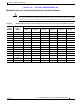


Table Of Contents
- Cisco Aironet 1240AG Series Access Point Hardware Installation Guide
- Contents
- Preface
- Overview
- Installing the Access Point
- Safety Information
- Warnings
- Unpacking the Access Point
- Basic Installation Guidelines
- Before Beginning the Installation
- Installation Summary
- Mounting Overview
- Mounting on a Horizontal or Vertical Surface
- Mounting Below a Suspended Ceiling
- Mounting Above a Suspended Ceiling
- Mounting Access Point on a Desktop or Shelf
- Connecting the Ethernet and Power Cables
- Powering Up the Access Point
- Cable Security Bracket
- Attaching the Access Point to the Mounting Plate
- Securing the Access Point
- Securing the Access Point to the Mounting Plate
- Configuring the Access Point for the First Time
- Using the Web-Browser Interface
- Using the Command-Line Interface
- Troubleshooting
- Translated Safety Warnings
- Declarations of Conformity and Regulatory Information
- Manufacturers Federal Communication Commission Declaration of Conformity Statement
- Department of Communications—Canada
- European Community, Switzerland, Norway, Iceland, and Liechtenstein
- Declaration of Conformity for RF Exposure
- Guidelines for Operating Cisco Aironet Access Points in Japan
- Declaration of Conformity Statements
- Declaration of Conformity Statements for European Union Countries
- Access Point Specifications
- Channels and Power Levels
- Console Cable Pinouts
- Glossary
- Index

Draft 1A - CISCO CONFIDENTIAL
D-6
Cisco Aironet 1240AG Series Access Point Hardware Installation Guide
OL-7293-01
Appendix D Channels and Power Levels
Channels and Maximum Power Levels
Caution To avoid exceeding maximum conducted power levels in the EMEA (-E) and Israel (–) regulatory
domains when using a IEEE 802.11a radio with 6.0- to 9.5-dBi external 5-MHz antennas, you must
manually set the access point output power level as shown in Table D-5.
Table D-5 Maximum Power Levels for IEEE 802.11a Radio in the EMEA(–E) and Israel (–I) Regulatory Domains
Channel
Identifier
Center
Frequency
(MHz)
Maximum Power Levels (dBm)
3.5 dBi Antenna 4.5 dBi Antenna 6.0 dBi Antenna 7.0 dBi Antenna 9.5 dBi Antenna
UNII-1 (5150-5250 MHz)
345170 –––––
36 5180 17 17 15 15 11
385190 –––––
40 5200 17 17 15 15 11
425210 –––––
44 5220 17 17 15 15 11
465230 –––––
48 5240 17 17 15 15 11
5250 to 5350 MHz
52 5260 17 17 15 15 11
56 5280 17 17 15 15 11
60 5300 17 17 15 15 11
64 5320 17 17 15 15 11
5470 to 5725 MHz
100 5500 17 17 17 17 17
104 5520 17 17 17 17 17
108 5540 17 17 17 17 17
112 5560 17 17 17 17 17
116 5580 17 17 17 17 17
120 5600 17 17 17 17 17
124 5620 17 17 17 17 17
128 5640 17 17 17 17 17
132 5660 17 17 17 17 17
136 5680 17 17 17 17 17
140 5700 17 17 17 17 17
5725 to 5850 MHz
1495745–––––
1535765–––––
1575785–––––
1615805–––––
1655825–––––