
Installation Guide
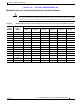


Table Of Contents
- Cisco Aironet 1240AG Series Access Point Hardware Installation Guide
- Contents
- Preface
- Overview
- Installing the Access Point
- Safety Information
- Warnings
- Unpacking the Access Point
- Basic Installation Guidelines
- Before Beginning the Installation
- Installation Summary
- Mounting Overview
- Mounting on a Horizontal or Vertical Surface
- Mounting Below a Suspended Ceiling
- Mounting Above a Suspended Ceiling
- Mounting Access Point on a Desktop or Shelf
- Connecting the Ethernet and Power Cables
- Powering Up the Access Point
- Cable Security Bracket
- Attaching the Access Point to the Mounting Plate
- Securing the Access Point
- Securing the Access Point to the Mounting Plate
- Configuring the Access Point for the First Time
- Using the Web-Browser Interface
- Using the Command-Line Interface
- Troubleshooting
- Translated Safety Warnings
- Declarations of Conformity and Regulatory Information
- Manufacturers Federal Communication Commission Declaration of Conformity Statement
- Department of Communications—Canada
- European Community, Switzerland, Norway, Iceland, and Liechtenstein
- Declaration of Conformity for RF Exposure
- Guidelines for Operating Cisco Aironet Access Points in Japan
- Declaration of Conformity Statements
- Declaration of Conformity Statements for European Union Countries
- Access Point Specifications
- Channels and Power Levels
- Console Cable Pinouts
- Glossary
- Index

Draft 1A - CISCO CONFIDENTIAL
E-2
Cisco Aironet 1240AG Series Access Point Hardware Installation Guide
OL-7293-01
Appendix E Console Cable Pinouts
Overview
Overview
The access point requires a special serial cable that connects the access point serial console port (RJ-45
connector) to your PC’s COM port (DB-9 connector). This cable can be purchased from Cisco (part
number AIR-CONCAB1200) or can be built using the pinouts in this appendix.
Console Port Signals and Pinouts
Use the console RJ-45 to DB-9 serial cable to connect the access point’s console port to the COM port
of your PC running a terminal emulation program.
Note Both the Ethernet and console ports use RJ-45 connectors. Be careful to avoid accidently connecting the
serial cable to the Ethernet port connector.
Note After completing your configuration changes, you must remove the serial console cable from the access
point.
Table 1 lists the signals and pinouts for the console RJ-45 to DB-9 serial cable.
Table 1 Signals and Pinouts for a Console RJ-45 to DB-9 Serial Cable
Console Port PC COM Port
RJ-45 DB-9
Pins Signals Pins Signals
1NC
1
1. NC indicates not connected.
––
2NC
1
––
3TXD
2
2. TXD indicates transmit data.
2RXD
3
3. RXD indicates receive data.
4GND
4
4. GND indicates ground
5GND
4
5GND
3
5GND
4
6RXD
5
3TXD
2
7NC
1
––
8NC
1
––