You'll be entered into a quarterly drawing for free Cisco Press books by returning this survey! Cisco is dedicated to customer satisfaction and would like to hear your thoughts on these printed manuals. Please visit the Cisco Product Comments on-line survey at www.cisco.com/go/crc to submit your comments about accessing Cisco technical manuals. Thank you for your time.
FIRST-CLASS MAIL PERMIT NO.
Cisco 12016, Cisco 12416, and Cisco 12816 Router Installation and Configuration Guide Corporate Headquarters Cisco Systems, Inc. 170 West Tasman Drive San Jose, CA 95134-1706 USA http://www.cisco.
THE SPECIFICATIONS AND INFORMATION REGARDING THE PRODUCTS IN THIS MANUAL ARE SUBJECT TO CHANGE WITHOUT NOTICE. ALL STATEMENTS, INFORMATION, AND RECOMMENDATIONS IN THIS MANUAL ARE BELIEVED TO BE ACCURATE BUT ARE PRESENTED WITHOUT WARRANTY OF ANY KIND, EXPRESS OR IMPLIED. USERS MUST TAKE FULL RESPONSIBILITY FOR THEIR APPLICATION OF ANY PRODUCTS.
About This Guide Audience The Cisco 12016, Cisco 12416, and Cisco 12816 Router Installation and Configuration Guide is written for hardware installers and system administrators of Cisco routers. This publication assumes that the user has a substantial background in installing and configuring router and switch-based hardware. The reader should also be familiar with electronic circuitry and wiring practices, and have experience as an electronic or electromechanical technician.
About This Guide Document Organization Document Organization This installation and configuration guide is organized into the following chapters and appendixes: • Chapter 1, “Product Overview,”provides an introduction to the major components of the Cisco 12016, Cisco 12416, and Cisco 12816 series routers. • Chapter 2, “Preparing for Installation,” describes safety considerations, required tools and equipment, an overview of the installation, and procedures to perform before the installation.
About This Guide Document Conventions Document Conventions This publication uses the following conventions: • Ctrl represents the key labeled Control. For example, the key combination Ctrl-Z means hold down the Control key while you press the z key. Command descriptions use these conventions: • Examples that contain system prompts denote interactive sessions, indicating the commands that you should enter at the prompt. The system prompt indicates the current level of the EXEC command interpreter.
About This Guide Obtaining Documentation Timesaver Warning Means the described action saves time. You can save time by performing the action described in the paragraph. This warning symbol means danger. You are in a situation that could cause bodily injury. Before you work on any equipment, be aware of the hazards involved with electrical circuitry and be familiar with standard practices for preventing accidents.
About This Guide Obtaining Documentation Product Documentation DVD Cisco documentation and additional literature are available in the Product Documentation DVD package, which may have shipped with your product. The Product Documentation DVD is updated regularly and may be more current than printed documentation. The Product Documentation DVD is a comprehensive library of technical product documentation on portable media.
About This Guide Documentation Feedback • Instructions for ordering documentation using the Ordering tool are at this URL: http://www.cisco.com/univercd/cc/td/doc/es_inpck/pdi.htm • Nonregistered Cisco.com users can order documentation through a local account representative by calling Cisco Systems Corporate Headquarters (California, USA) at 408 526-7208 or, elsewhere in North America, by calling 1 800 553-NETS (6387).
About This Guide Cisco Product Security Overview A current list of security advisories and notices for Cisco products is available at this URL: http://www.cisco.com/go/psirt If you prefer to see advisories and notices as they are updated in real time, you can access a Product Security Incident Response Team Really Simple Syndication (PSIRT RSS) feed from this URL: http://www.cisco.com/en/US/products/products_psirt_rss_feed.
About This Guide Obtaining Technical Assistance The link on this page has the current PGP key ID in use. Obtaining Technical Assistance Cisco Technical Support provides 24-hour-a-day award-winning technical assistance. The Cisco Technical Support & Documentation website on Cisco.com features extensive online support resources. In addition, if you have a valid Cisco service contract, Cisco Technical Assistance Center (TAC) engineers provide telephone support.
About This Guide Obtaining Technical Assistance Submitting a Service Request Using the online TAC Service Request Tool is the fastest way to open S3 and S4 service requests. (S3 and S4 service requests are those in which your network is minimally impaired or for which you require product information.) After you describe your situation, the TAC Service Request Tool provides recommended solutions.
About This Guide Obtaining Additional Publications and Information Severity 3 (S3)—Operational performance of your network is impaired, but most business operations remain functional. You and Cisco will commit resources during normal business hours to restore service to satisfactory levels. Severity 4 (S4)—You require information or assistance with Cisco product capabilities, installation, or configuration. There is little or no effect on your business operations.
About This Guide Obtaining Additional Publications and Information solve them, using real-world case studies and business strategies to help readers make sound technology investment decisions. You can access iQ Magazine at this URL: http://www.cisco.com/go/iqmagazine or view the digital edition at this URL: http://ciscoiq.texterity.
About This Guide Obtaining Additional Publications and Information Cisco 12016, Cisco 12416, and Cisco 12816 Router Installation and Configuration Guide xxiv OL-11495-01
CONTENTS About This Guide xiii Audience xiii Purpose xiii Document Organization xiv Document Conventions xv Obtaining Documentation xvi Cisco.
Contents AC Power Supplies 1-10 DC Power Shelf 1-12 DC Power Supplies 1-15 Chassis Card Cages 1-17 Upper Card Cage 1-17 Lower Card Cage 1-18 Switch Fabric Card Cage 1-18 Switch Fabric Overview 1-19 Switch Fabric Card Functionality 1-19 Clock Scheduler Cards 1-20 Switch Fabric Cards 1-20 Alarm Card, Line Card, and Rout Processor Overview 1-21 Alarm Cards 1-21 Line Cards 1-23 Route Processor Selection 1-24 Gigabit Route Processor Overview 1-24 GRP PCMCIA Card Slots and Status LEDs 1-25 GRP Reset Switch 1-27
Contents PRP Reset Switch 1-37 PRP Alphanumeric Message Displays 1-38 PRP Memory Components 1-39 PRP SDRAM 1-41 PRP SRAM 1-41 PRP NVRAM 1-42 PRP Flash Memory 1-42 Upper and Lower Cable Management Brackets 1-43 Blower Module 1-44 CHAPTER 2 Preparing for Installation 2-1 Safety Guidelines 2-2 Safety with Equipment 2-2 Safety with Electricity 2-3 Preventing Electrostatic Discharge Damage 2-4 Lifting Guidelines 2-6 Compliance and Safety Information 2-6 Laser Safety 2-7 Site Requirement Guidelines 2-7 Rack-M
Contents Site Wiring Guidelines 2-24 GRP Port Connection Guidelines 2-25 GRP Auxiliary and Console Port Connections 2-26 GRP Auxiliary Port Signals 2-27 GRP Console Port Signals 2-28 GRP Ethernet Port Connections 2-29 GRP RJ-45 Ethernet Connections 2-31 GRP MII Ethernet Connections 2-33 PRP Port Connection Guidelines 2-36 PRP Auxiliary and Console Port Connection Guidelines 2-36 PRP Auxiliary Port Signals 2-38 PRP Console Port Signals 2-39 PRP Ethernet Connections 2-40 PRP RJ-45 Ethernet Connections 2-42 A
Contents Connecting to the Front Grounding Receptacle 3-22 Connecting to the Top Rear Receptacle 3-24 Attaching the Vertical Cable-Management Trough 3-25 Connecting Line Card Network Interface Cables 3-27 Connecting GRP Route Processor Cables Connecting to the GRP Console Port Connecting to the GRP Auxiliary Port Connecting to the GRP Ethernet Port RJ-45 Connection 3-35 MII Connection 3-35 3-31 3-32 3-33 3-33 Connecting PRP Route Processor Cables 3-36 Connecting to the PRP Console Port 3-37 Connecting to
Contents Booting from the Cisco IOS Software Image 4-12 Configuring the Router 4-14 Cisco IOS User Interface 4-15 Cisco IOS User Interface Command Modes 4-15 User EXEC Mode 4-16 Privileged EXEC Mode 4-16 Global Configuration Mode 4-17 Using Setup for Configuration Changes 4-18 Configuring Global Parameters Using the Setup Facility 4-22 Configuring Network Interfaces 4-24 Checking the Software Version Number and Installed Interfaces 4-26 Using Global Configuration Mode 4-27 Verifying Running Configuration F
Contents squeeze Command 4-51 Booting from Flash Memory 4-52 Copying Image Files to or From Flash Memory 4-52 Copying a Cisco IOS Software Image into a Flash Memory Card 4-54 Copying Cisco IOS Software Images Between Flash Memory Cards 4-56 Copying System Configuration Files Between RP Memory and a Flash Memory Card 4-57 Booting a New Cisco IOS Software Image from a Flash Memory Card 4-62 Recovering from Locked Blocks in Flash Memory Cards 4-62 Post-Installation Procedures 4-63 CHAPTER 5 Troubleshooting
Contents Analyzing the Data 5-30 crc16 Output 5-30 Grant Parity and Request Errors 5-33 Properly Seating Switch Fabric Cards 5-35 Troubleshooting the Cooling Subsystem 5-36 Blower Module Operation 5-38 Power Supply Operation 5-38 Overtemperature Conditions 5-39 Isolating Cooling Subsystem Problems 5-39 CHAPTER 6 Router Field Diagnostics 6-1 Diagnostics Overview 6-2 Downloading the Diagnostic Image 6-3 Field-Programmable Gate Array Overview 6-3 Upgrading an FPGA Image on a Line Card 6-5 Using the diag Co
Contents Removing and Installing the Front Covers and Bezel Extenders on Original Cisco 12000 Series Routers 7-3 Removing the Front Covers 7-3 Installing the Front Covers 7-4 Attaching Bezel Extenders to the Front Cover 7-6 Removing and Replacing the Air Filter Door Front Cover 7-9 Removing and Installing Front Doors on Cisco 12016 Enhanced Series Routers 7-13 Cleaning or Replacing the Chassis Air Filter 7-17 Cleaning or Replacing the Chassis Air Filter on Cisco 12016 Original Series Routers 7-18 Cleaning
Contents Removing and Replacing Cards from the Chassis 7-79 Removing and Replacing RP and Line Cards from the Upper and Lower Card Cages 7-79 Removing and Replacing an Alarm Card 7-81 Removing and Replacing Switch Fabric Cards 7-84 Upgrading the Switch Fabric 7-86 Upgrade Requirements 7-86 Upgrade Procedures 7-87 Removing and Installing a Chassis 7-88 Preparing the Replacement Chassis 7-90 Preparing the Installed Chassis for Removal 7-90 Removing and Installing System Components 7-91 Removing the Chassis f
C H A P T E R 1 Product Overview This chapter provides an overview of the Cisco 12016, Cisco 12416, and Cisco 12816 series routers. It contains physical descriptions of the router hardware and major components, as well as functional descriptions of the hardware-related features. Introduction The routers described in this guide are part of the Cisco 12016, Cisco 12416, and Cisco 12816 series routers and include: • The original Cisco 12016, Cisco 12416, and Cisco 12816 series routers.
Chapter 1 Product Overview Physical and Functional Description of Router Physical and Functional Description of Router The Cisco 12000 series router chassis is a sheet-metal enclosure that houses router components. The major components consist of three power supplies, upper and lower line card cages, a switch fabric card cage, and upper and lower blower modules. Power is distributed to these components over the chassis backplane.
Chapter 1 Product Overview Physical and Functional Description of Router Figure 1-1 Cisco 12016 Series Router Components—Front View PWR OK Power shelf and power supplies PWR OK FAULT PWR OK FAULT TEMP FAULT TEMP I LIM TEMP I LIM I LIM Upper blower module CDHNT CDHNT RA RA LOOP DOWN LOOP DOWN CD CD LA LA Upper cable management bracket TX TX 0 0 RX RX TX TX 0 1 1 RX RX TX TX 2 2 E IER T TIV RR PK AC CA RX EJE RX RX CT 3 SE T TX TX E IER LL TIV RR CE AC CA RX
Chapter 1 Product Overview Physical and Functional Description of Router AC and DC Power Subsystems A router ships with either an AC or DC powered system. Source power connects to the power shelf at the back of the chassis which route power to the power supplies, also referred to as power entry modules (PEMs).
Chapter 1 Product Overview Physical and Functional Description of Router Standard AC-Input Power Subsystem —2000 W PWR OK FAULT PWR OK FAULT PWR OK TEMP FAULT I LIM TEMP I LIM TEMP I LIM Caution 26198 Figure 1-2 A router equipped with the standard AC power subsystem must be operated with three power supplies installed in the power shelf at all times for electromagnetic compatibility (EMC).
Chapter 1 Product Overview Physical and Functional Description of Router AC power to the router is provided through power cords connected from AC power outlets to connectors on back of the power shelf as shown in Figure 1-3.
Chapter 1 Product Overview Physical and Functional Description of Router Optional AC Power Shelf The power subsystem consists of a double-level AC-input power shelf with bays for 4 AC-input power supplies. Figure 1-4 shows the optional power shelf housing original series 2000 W power supplies. It attaches to the top of the router chassis and is secured to the chassis the same way as the standard AC-input power shelf. Note A router equipped with the optional AC-input power subsystem stands 77.
Chapter 1 Product Overview Physical and Functional Description of Router Figure 1-4 Optional AC-Input Power Subsystem—2000 W PWR OK FAULT TEMP I LIM PWR OK FAULT TEMP PWR OK FAULT TEMP I LIM PWR OK FAULT TEMP I LIM Caution 27837 I LIM A router equipped with the optional AC power subsystem must be operated with 4 power supplies installed in the power shelf at all times for electromagnetic compatibility (EMC).
Chapter 1 Product Overview Physical and Functional Description of Router AC power to the router is provided through power cords connected from AC power outlets to the connectors on the back of the power shelf as shown in Figure 1-5.
Chapter 1 Product Overview Physical and Functional Description of Router AC Power Supplies Each AC PEM converts 200 to 240 VAC into -48 VDC, which is distributed through the chassis backplane to all cards, RPs, and the blower modules. Figure 1-6 identifies the components of a 2000 W AC power supply.
Chapter 1 Product Overview Physical and Functional Description of Router Figure 1-7 identifies the components of a 2500 W AC power supply. Figure 1-7 2500 W AC Power Supply Components 1 2 Pwr Ok 1 Fault Fault Ejector handle Temp OC 129495 Pwr Ok Temp 2 OC Captive screw The status LEDs on an AC PEM provide information about the current operational status of the power supply: • PWR OK (green)—Indicates that the power supply module is operating normally.
Chapter 1 Product Overview Physical and Functional Description of Router • ILMI (yellow)—Indicates the PEM is operating in a current-limiting condition. For additional information about troubleshooting AC PEMs, see the “Troubleshooting the AC-Input Power Subsystem” section on page 5-6. DC Power Shelf A DC-input power subsystem consists of a DC-input power shelf that houses 4 (2000 W or 2400 W) DC PEMs that provide full redundant power to the router.
Chapter 1 Product Overview Physical and Functional Description of Router Figure 1-8 DC-Input Power Shelf—2000 Watts PWR OK PWR OK PWR OK FAULT FAULT TEMP FAULT TEMP TEMP TEMP Caution Note 26201 PWR OK FAULT A router configured for source DC operation must be operated with 4 DC-input PEMs installed at all times for electromagnetic compatibility (EMC).
Chapter 1 Product Overview Physical and Functional Description of Router Figure 1-9 DC-Input Power Shelf Connections B1 B2+ B2- B1+ B1- Ground 27964 A1- A1+ A2- A2+ Cover with slotted screw hole; fastens to standoff in middle of cable connection area Cisco 12016, Cisco 12416, and Cisco 12816 Router Installation and Configuration Guide 1-14 OL-11495-01
Chapter 1 Product Overview Physical and Functional Description of Router DC Power Supplies Each DC PEM operates from a nominal source DC voltage of –48 to –60 VDC and requires a dedicated 60 amp service. Figure 1-10 identifies the components of a 2000 W DC power supply.
Chapter 1 Product Overview Physical and Functional Description of Router Figure 1-11 identifies the components of a 2400 W DC power supply. Figure 1-11 2400 W DC Power Supply Components 2 1 3 PWR OK FAULT TEMP OC 4 FAULT TEMP OC 129494 PWR OK 1 Handle 3 Ejector lever 2 Fan 4 Power switch The status LEDs on a DC PEM provide information about the current operational status of the power supply: • PWR OK (green)—Indicates that the power supply module is operating normally.
Chapter 1 Product Overview Chassis Card Cages For additional information about troubleshooting DC PEMs, see the “Troubleshooting the DC-Input Power Subsystem” section on page 5-10. Chassis Card Cages There are three integral card cages in the chassis: the upper card cage, the lower card cage, and the switch fabric card cage (see Figure 1-1). Upper Card Cage The upper card cage has eight user-configurable slots that support a combination of line cards, an alarm card, and an RP.
Chapter 1 Product Overview Chassis Card Cages Lower Card Cage The lower card cage also has eight user-configurable slots that support additional line cards, an alarm card, and an optional, redundant RP. Note The lower card cage is an inverted, or head-down, copy of the upper card cage, which means that cards are installed in an inverted or head-down orientation. The orientation of the slots is opposite that of the upper card cage. • Slot 8—The far left slot is reserved for an optional redundant RP.
Chapter 1 Product Overview Switch Fabric Overview Switch Fabric Overview The switch fabric provides synchronized gigabit-speed connections between line cards and the RP. The switch fabric card cage is located behind the air filter door and consists of 2 clock and scheduler cards (CSCs) and 3 switch fabric cards (SFCs). One CSC and the 3 SFCs are the active switch fabric; the second CSC provides redundancy for the other 4 cards.
Chapter 1 Product Overview Switch Fabric Overview The router also ships with a blank switch fabric card installed in the far left (non-working) slot of the switch fabric card cage. The blank filler panel balances the air flow through the switch fabric card cage which helps maintain proper air flow through the chassis. Caution Do not remove the blank filler panel unless instructed to do so by a Cisco support representative.
Chapter 1 Product Overview Alarm Card, Line Card, and Rout Processor Overview Alarm Card, Line Card, and Rout Processor Overview This section provides general information about alarm cards, line cards and types of route processors installed in the router. Note The Cisco 12000 series router supports online insertion and removal (OIR), allowing you to remove and replace a card while the router remains powered on.
Chapter 1 Product Overview Alarm Card, Line Card, and Rout Processor Overview Some of the functions that the alarm cards provide are: • Supplies +5 VDC to the MBus modules on router components (see AC and DC Power Subsystems, page 1-4). • Displays alarm severity levels (critical, major, and minor) detected by the system through the MBus. • Provides connections for an external alarm system. • Displays the status of the alarm cards, clock scheduler cards, and switch fabric cards.
Chapter 1 Product Overview Alarm Card, Line Card, and Rout Processor Overview Figure 1-12 Alarm Card Components and LEDs C C CS IL FA D LE IL FA D E L AB Critical, major, and minor alarm LEDs AL JOR OR IN MA M IC IT AL JOR OR IN MA M 2 1 Pin 1 C CS CR 0 EN T O/L AC ALARM Pin 25 Audio alarm cutoff switch IL FA D LE AB EN IL FA D LE AB EN 0 1 26867 Handle 1 0 AB EN SF C SF 0 1 2 ALARM Clock and scheduler card and switch fabric card LEDs IC IT CR Line Cards Up to 15 C
Chapter 1 Product Overview Alarm Card, Line Card, and Rout Processor Overview Route Processor Selection Two types of RPs are available: a Gigabit Route Processor (GRP) or a Performance Route Processor (PRP). The GRP is the route processor that shipped with earlier Cisco 12000 series routers; the PRP is the route processor shipping with all current Cisco 12000 series routers. You cannot mix GRPs with PRPs. If you install a redundant RP, it must be the same type as the primary RP.
Chapter 1 Product Overview Alarm Card, Line Card, and Rout Processor Overview RJ -4 5 MI GIGABIT ROUTE PROCESSOR 5 6 129306 4 I CO LL RX LIN K CO NS OL E 3 TX ET RE S 2 AU X EJ EC T 1 SL SL OT OT -0 -1 Figure 1-13 Gigabit Route Processor Front Panel 7 1 PCMCIA flash card slots, eject buttons, and slot LEDs 5 RJ-45 Ethernet port and data status LEDs 2 Reset button 6 MII Ethernet connection 3 Auxiliary serial port 7 Alphanumeric message displays 4 Console serial port GRP PCM
Chapter 1 Product Overview Alarm Card, Line Card, and Rout Processor Overview Figure 1-14 Slot Activity LEDs—Front Panel T EC EJ -1 OT SL -0 OT SL 129254 T SE RE X AU Cisco 12016, Cisco 12416, and Cisco 12816 Router Installation and Configuration Guide 1-26 OL-11495-01
Chapter 1 Product Overview Alarm Card, Line Card, and Rout Processor Overview GRP Reset Switch Access to the (soft) reset switch is through a small opening in the GRP front panel. To press the switch, insert a paper clip or similar small pointed object into the opening (see Figure 1-13 on page 1-25). Caution The reset switch is not a mechanism for resetting the GRP and reloading the Cisco IOS image. It is intended for software development use only.
Chapter 1 Product Overview Alarm Card, Line Card, and Rout Processor Overview GRP Auxiliary and Console Ports The auxiliary and console ports on the GRP are EIA/TIA-232 (also known as RS-232) asynchronous serial ports. These ports connect external devices to monitor and manage the system. Caution • The auxiliary port—A (male) plug that provides a data terminal equipment (DTE) interface.
Chapter 1 Product Overview Alarm Card, Line Card, and Rout Processor Overview The transmission speed of the Ethernet port is not user-configurable. You set the speed through an autosensing scheme on the GRP which is determined by the network that the Ethernet port is connected to. However, even at an autosensed data transmission rate of 100 Mbps, the Ethernet port can only provide a usable bandwidth of substantially less than 100 Mbps.
Chapter 1 Product Overview Alarm Card, Line Card, and Rout Processor Overview GRP Alphanumeric Message Displays The alphanumeric message displays are organized in two rows of four LED characters (Figure 1-16). Figure 1-16 Alphanumeric Message Displays—Front Panel PROCESSOR Upper alphanumeric LED display (four digits) H10780 Lower alphanumeric LED display (four digits) The alphanumeric message displays show router status messages during the boot process, and after the boot process is complete.
Chapter 1 Product Overview Alarm Card, Line Card, and Rout Processor Overview GRP Memory Components This section describes various types of memory used on the GRP to support router functions. Table 1-1 provides a quick reference of the different types of memory, and Figure 1-17 shows the location on the GRP board.
Chapter 1 Product Overview Alarm Card, Line Card, and Rout Processor Overview Figure 1-17 GRP Memory Locations U42 Bank 2 DRAM DIMMs Bank 1 U39 Flash SIMM EC T EJ -1 OT SL -0 OT SL RE SE CO T X AU LIN K TX LL RJ RX M II -4 129255 U17 5 GIGABIT ROUTE PROCESSOR PCMCIA slot-0 and slot-1 Cisco 12016, Cisco 12416, and Cisco 12816 Router Installation and Configuration Guide 1-32 OL-11495-01
Chapter 1 Product Overview Alarm Card, Line Card, and Rout Processor Overview GRP DRAM The GRP uses Extended Data-Out (EDO) Dynamic Random Access Memory (DRAM) to store routing tables, protocols, network accounting applications, and to run Cisco IOS software. Table 1-2 lists the DRAM configurations for the GRP.
Chapter 1 Product Overview Alarm Card, Line Card, and Rout Processor Overview GRP Flash Memory Use flash memory to store multiple Cisco IOS software and microcode images that you can use to operate the router. You can download new images to flash memory over the network (or from a local server) to replace an existing image, or to add it as an additional image. The router can be booted (manually or automatically) from any of the stored images in flash memory.
Chapter 1 Product Overview Alarm Card, Line Card, and Rout Processor Overview PRP PCMCIA Card Slots and Status LEDs Two PCMCIA card slots (slot 0 and slot 1) provide the PRP with additional flash memory capacity. All combinations of different flash devices are supported by the PRP. You can use ATA flash disks, Type 1 or Type 2 linear flash memory cards, or a combination of the two. Note The PRP only supports +5.2 VDC flash memory devices. It does not support +3.3 VDC PCMCIA devices.
Chapter 1 Product Overview Alarm Card, Line Card, and Rout Processor Overview The following LEDs on the front panel indicate traffic status and port selection (Figure 1-19): • LINK, EN, TX, RX—Indicate link activity (LINK), port enabled (EN), data transmission (TX), and data reception (RX). • PRIMARY—Indicates which Ethernet port is selected (ETH 0 or ETH 1). Note Because both ports are supported on the PRP, ETH 0 is always on. ETH 1 lights when it is selected.
Chapter 1 Product Overview Alarm Card, Line Card, and Rout Processor Overview PRP Reset Switch Access to the (soft) reset switch is through a small opening in the PRP front panel (see Figure 1-18). To press the switch, insert a paper clip or similar small pointed object into the opening. Caution The reset switch is not a mechanism for resetting the PRP and reloading the Cisco IOS image. It is intended for software development use only.
Chapter 1 Product Overview Alarm Card, Line Card, and Rout Processor Overview PRP Alphanumeric Message Displays The alphanumeric message displays are organized in two rows of four LED characters each (Figure 1-20).
Chapter 1 Product Overview Alarm Card, Line Card, and Rout Processor Overview PRP Memory Components This section describes various types of memory used on the PRP to support router functions. Table 1-3 provides a quick reference of the different types of memory, and Figure 1-21 shows the location on the PRP board.
Chapter 1 Product Overview Alarm Card, Line Card, and Rout Processor Overview Figure 1-21 PRP Memory Locations U18 Flash SIMM Bank 2 DRAM DIMMs Bank 1 P3 U15 ETH 0 -1 OT SL -0 OT SL TX AUX K LIN TX T PRIMARY CONSOLE RX EN SE K LIN RE PRIMARY ETH 1 RX EN PERFORMANCE ROUTE PROCESSOR 1 (PRP-1) PCMCIA slot-1 and slot-2 (behind cover) 129256 T EC EJ Cisco 12016, Cisco 12416, and Cisco 12816 Router Installation and Configuration Guide 1-40 OL-11495-01
Chapter 1 Product Overview Alarm Card, Line Card, and Rout Processor Overview PRP SDRAM The PRP uses Error Checking and Correction (ECC) Synchronized Dynamic Random Access Memory (SDRAM) to store routing tables, protocols, network accounting applications, and to run Cisco IOS software. Table 1-4 lists the DRAM configurations for the PRP. If you are using: • One DIMM—Bank 1 (U15) must be populated first. • Two DIMMs—You cannot mix memory sizes; both banks must contain the same size DIMM.
Chapter 1 Product Overview Alarm Card, Line Card, and Rout Processor Overview PRP NVRAM Non-volatile Random Access Memory (NVRAM) provides 2 MB of memory for system configuration files, software register settings, and environmental monitoring logs. Built-in lithium batteries retain the contents of NVRAM for a minimum of 5 years. NVRAM is not user configurable and cannot be upgraded in the field.
Chapter 1 Product Overview Alarm Card, Line Card, and Rout Processor Overview Upper and Lower Cable Management Brackets Cisco 12010, Cisco 12410, and Cisco 12810 series routers include upper and lower cable management brackets that work together with individual line card cable management brackets to organize interface cables entering and exiting the router (see Figure 1-1).
Chapter 1 Product Overview Blower Module Blower Module The router has two blower modules to distribute air within the chassis. One blower module is located above the upper card cage; the second blower module is located below the lower card cage (see Figure 1-1). Each blower module contains three variable speed fans and a controller card.
Chapter 1 Product Overview Blower Module Figure 1-23 Cooling Air Flow Power supply shelf Air exhaust Top blower module (Plenum) Upper card cage Air filter Room air Middle card cage Lower card cage (Plenum) Bottom blower module Rear 26204 Front Air exhaust To ensure that there is adequate air flow to prevent overheating inside the card cages keep the front and back of the router unobstructed. We recommend at least 6 inches (15.24 cm) of clearance.
Chapter 1 Product Overview Blower Module Caution You should inspect and clean the air filter one time per month (more often in dusty environments). Do not operate the router without an air filter installed. The blower module controller card monitors and controls operation of three variable-speed fans in the blower modules.
C H A P T E R 2 Preparing for Installation Before installing your router, consider power and cabling requirements that must be in place at your installation site, special equipment for installing the router, and the environmental conditions your installation site must meet to maintain normal operation. This chapter guides you through the process of preparing for router installation.
Chapter 2 Preparing for Installation Safety Guidelines Safety Guidelines Before you perform any procedure in this publication, review the safety guidelines in this section to avoid injuring yourself or damaging the equipment. In addition, be sure to review the safety warnings listed in the Regulatory Compliance and Safety Information for Cisco 12000 Series Internet Routers publication that accompanied your router before you begin router installation.
Chapter 2 Preparing for Installation Safety Guidelines Safety with Electricity • The installation shall be in compliance with national and local electrical codes: in the United States, National Fire Protection Association (NFPA) 70, United States National Electrical Code; in Canada, Canadian Electrical Code, part I, CSA C22.1; in other countries, International Electrotechnical Commission (IEC) 60364, part 1 through part 7.
Chapter 2 Preparing for Installation Safety Guidelines Preventing Electrostatic Discharge Damage Many router components can be damaged by static electricity. Not exercising the proper electrostatic discharge (ESD) precautions can result in intermittent or complete component failures. To minimize the potential for ESD damage, always use an ESD-preventive antistatic wrist strap (or ankle strap) and ensure that it makes good skin contact.
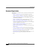
26208 CD TX TX 0 0 RX RX TX 0 TX 1 1 RX RX 2 2 VE TI RR AC CA RX R IE T PK TX TX RX RX 1 TX TX 3 3 RX TX 4 4 RX RX R VE IE T TI RR PK AC CA RX TX L R R CA JO NO ITI MA MI CR RX TX TX 2 5 5 RX LT O/ AC RX 6 RX R IE T PK VE TI RR AC CA RX TX ALARM TX 3 7 RX 8 RX R VE IE T TI RR PK AC CA RX TX TX 9 IL FA D LE AB EN RX TX 10 RX IL FA D LE AB EN TX 0 11 P/H/F 1 C CS 0 1 ALARM 2 C SF Q OC-3/STM-POS 6DS3–SMB P/H/F RX12DS3–SMB ROUTE PROCESSO
Chapter 2 Preparing for Installation Safety Guidelines Lifting Guidelines A fully configured router can weigh as much as 275 pounds (lb) (124.74 kilograms (kg)), while an empty chassis weighs 125 lb (56.7 kg). These systems are not intended to be moved frequently. Before you install the router, ensure that your site is properly prepared so you can avoid having to move the router later to accommodate power sources and network connections.
Chapter 2 Preparing for Installation Site Requirement Guidelines Laser Safety Some line cards are equipped with ports that can emit hazardous laser radiation from the aperture when there is no cable connected to the port. This invisible radiation can cause eye injury if you stare into the port. Warning To avoid eye injury, never stare into open line card ports.
Chapter 2 Preparing for Installation Site Requirement Guidelines Equipment Rack Types 27959 Figure 2-2 a b c Enclosed Rack Figure 2-2a shows a free-standing, enclosed rack with two mounting posts in the front. The router should not be installed in this type of enclosed rack, because the router requires an unobstructed flow of cooling air to maintain acceptable operating temperatures for its internal components.
Chapter 2 Preparing for Installation Site Requirement Guidelines Telco Rack Figure 2-2c shows a telco-type rack. The telco-type rack is an open frame consisting of two posts tied together by a cross-bar at the top and a floor stand at the bottom. This type of rack is usually secured to the floor and sometimes to an overhead structure or wall for additional stability. The router chassis can be installed in the telco-type rack either in a front-mounted position or a center-mounted position (Figure 2-3).
Chapter 2 Preparing for Installation Site Requirement Guidelines Figure 2-3 Front-Mounted and Center-Mounted Installation in a Telco Rack Front-mount rail Cisco 12016 chassis 27958 Center-mount bracket Front-mounted chassis in telco rack Center-mounted chassis in telco rack Cisco 12016, Cisco 12416, and Cisco 12816 Router Installation and Configuration Guide 2-10 OL-11495-01
Chapter 2 Preparing for Installation Site Requirement Guidelines Site Layout and Equipment Dimensions To help maintain trouble-free operation, adhere to the following precautions when planning your rack installation: • Ensure the site of the rack includes provisions for source AC or DC power, grounding, and network interface cables. • Allow sufficient space to work around the rack during the installation. You need: – At least 3 feet adjacent to the rack to move, align, and insert the chassis.
Chapter 2 Preparing for Installation Site Requirement Guidelines • Install the cable-management brackets included with the router to keep cables organized. Be sure to: – Use appropriate strain-relief methods to protect cables and equipment connections. – Make sure that cables from other equipment installed in the rack do not restrict access to the card cages. • To avoid noise interference in network interface cables, do not route them directly across or along power cables.
Chapter 2 Preparing for Installation Site Requirement Guidelines Figure 2-4 Router Chassis Footprint and Dimensions—Top View) 17.3 in. Back 20 in. Vertical rack-mounting flange (each side) 2.75 in. 2.01 in. 2 in. Front 18.75 in.
Chapter 2 Preparing for Installation Site Requirement Guidelines Figure 2-5 shows the footprint and outer dimensions of the enhanced version of router chassis. Figure 2-5 Enhanced Router Chassis Footprint and Dimensions—Top View 17.3 in. 17.963 in. 25.694 in. 18.950 in. 57090 7.731 in.
Chapter 2 Preparing for Installation Site Requirement Guidelines Air Flow Guidelines Cool air is circulated through the router chassis by two blower modules. The blower modules maintain acceptable operating temperatures for the internal components by drawing in cool air through the air filter in front of the switch fabric card cage (middle), and circulating the air through both card cages (Figure 2-6).
Chapter 2 Preparing for Installation Site Requirement Guidelines Figure 2-6 Air Flow Path through the Router - Side View Power supply shelf Air exhaust Top blower module (Plenum) Upper card cage Air filter Room air Middle card cage Lower card cage (Plenum) Bottom blower module Rear 26204 Front Air exhaust Cisco 12016, Cisco 12416, and Cisco 12816 Router Installation and Configuration Guide 2-16 OL-11495-01
Chapter 2 Preparing for Installation Site Requirement Guidelines Temperature and Humidity Guidelines The operating and nonoperating environmental site requirements are listed in Table A-4 on page A-4. The router normally operates within the ranges listed in Table A-4, however, if a temperature measurement is approaching a minimum or maximum parameter it indicates a potential problem.
Chapter 2 Preparing for Installation Site Requirement Guidelines AC-Powered Routers AC PEMs operate in the nominal range of 200 VAC to 240 VAC and require a minimum service of: • 20 A for operation in North America • 16 A for international operation • 13 A for operation in the UK Each of the AC power inputs requires separate dedicated branch circuit. For a list of the nominal and acceptable value ranges for source AC power, refer to Table A-2 on page A-3.
Chapter 2 Preparing for Installation Site Requirement Guidelines Table 2-1 lists power cord options. All AC-input power supply power cords measure 14 feet (4.3 m).
Chapter 2 Preparing for Installation Site Requirement Guidelines You must terminate DC power cables using cable lugs at the power shelf end. Ensure the lugs are dual-hole and that they are able to fit over M6 terminal studs at 0.625-inch (15.88-mm) centers (for example, Panduit Part Number LCD8-14A-L or equivalent). Figure 2-8 shows the type of lug required for the DC-input cable connections. Figure 2-8 DC Power Cable Lug All measurements in inches 2.24 End View 0.48 Ø 0.267 2 holes 0.
Chapter 2 Preparing for Installation Site Requirement Guidelines Figure 2-9 Typical Source DC Power Cabling Scheme for Power Shelf Bay B1 CO ground AC Central office primary & secondary DC power distribution Rectifiers Plant controls Batteries Battery plant Ground window Central office ground + – Ground + – 27963 Ground Cisco 12016, Cisco 12416, and Cisco 12816 Router Installation and Configuration Guide OL-11495-01 2-21
Chapter 2 Preparing for Installation Site Requirement Guidelines Caution DC PEMs contains circuitry to trip the breaker on the PEM if the PEM detects a reverse polarity condition. No damage should occur from reverse polarity, but you should correct a reverse polarity condition immediately. For a list of the nominal and acceptable value ranges for source DC power, refer to Table A-3 on page A-3.
Chapter 2 Preparing for Installation Site Requirement Guidelines 29183 Figure 2-10 Router Bonding and Grounding Receptacles—Top Rear Supplemental bonding and grounding receptacle Figure 2-11 Router Bonding and Grounding Receptacles—Front RX TX IL FA D LE AB EN 1 ROUTE PROCESSOR P/H/F FAST ETERNET 2 ALARM C SF OC-12/STM-4 ATM 1 6DS3–SMB P/H/F 0 RX12DS3–SMB C CS Q OC-3/STM-POS OC-48/STM-16-SCPOS 11 0 NEBS supplemental earth ground receptacle 28022 Air filter door Cisco 12016, Cisco 1
Chapter 2 Preparing for Installation Site Requirement Guidelines To ensure a satisfactory supplemental ground connection to the router, use the following parts: Note These parts are not available from Cisco, but are available from commercial vendors. • Two grounding lugs, which have two M6 bolt holes with 0.625 to 0.75-inch (15.86 to 19.05-mm) spacing between them, and a wire receptacle large enough to accept a 6-AWG or larger, multistrand copper wire.
Chapter 2 Preparing for Installation GRP Port Connection Guidelines Site wiring is unlikely to emit radio interference if you use twisted-pair cable with a good distribution of grounding conductors. Use a high-quality twisted-pair cable with one ground conductor for each data signal, when applicable. Give special consideration to the effect of a lightning strike in your vicinity, especially if the wiring exceeds the recommended distances, or if it passes between buildings.
Chapter 2 Preparing for Installation GRP Port Connection Guidelines GRP Auxiliary and Console Port Connections The GRP has two EIA/TIA-232 ports (Figure 2-12): • Auxiliary port— DB-25 plug, DTE-mode port for connecting a modem or other DCE device (such as a CSU/DSU or another router) to the GRP. • Console port—DB-25 receptacle, DCE-mode port for connecting a data terminal to perform the initial configuration of the router. Note The auxiliary and console ports are asynchronous serial ports.
Chapter 2 Preparing for Installation GRP Port Connection Guidelines Caution To maintain Class B EMI compliance, you must use shielded cables when connecting to the auxiliary and console ports of original GRPs (part numbers GRP= and GRP-B=). An updated version of the GRP-B= board (Rev. F0) does not require shielded cables for Class B compliance. GRP Auxiliary Port Signals The GRP auxiliary port is a DB-25 DTE port for connecting a modem or other DCE device to the router.
Chapter 2 Preparing for Installation GRP Port Connection Guidelines GRP Console Port Signals The GRP console port is a DB-25 DCE interface for connecting a DTE terminal device to the router. Both Data Set Ready (DSR) and Data Carrier Detect (DCD) signals are active when the router is powered on. The console port does not support modem control or hardware flow control and requires a straight-through EIA/TIA-232 cable.
Chapter 2 Preparing for Installation GRP Port Connection Guidelines GRP Ethernet Port Connections The GRP has the following two types of Ethernet connections (Figure 2-13): • RJ-45 media-dependent interface (MDI) • 40-pin, D-shell type media-independent interface (MII) Figure 2-13 GRP RJ-45 and MII Ethernet Connections NK LI LL CO RX TX II M To repeater or DTE H10736 MII cable GIGABIT ROUTE PROCESSOR To transceiver, repeater, or DTE 5 -4 RJ RJ-45 cable You can use either Ethernet connection,
Chapter 2 Preparing for Installation GRP Port Connection Guidelines The GRP Ethernet port does not provide external routing functions. Its primary roles are to act as a Telnet port into the router, and to boot or access Cisco IOS software images over a network to which the GRP Ethernet port is directly connected. Caution Cisco Express Forwarding (CEF) functions on these ports are switched off by default for security reasons.
Chapter 2 Preparing for Installation GRP Port Connection Guidelines GRP RJ-45 Ethernet Connections The RJ-45 Ethernet connection does not require an external transceiver. Figure 2-15 shows the pin orientation of the RJ-45 Ethernet port and the modular cable plug it accepts. H2936 Figure 2-15 GRP RJ-45 Ethernet Receptacle and Modular Plug 87654321 RJ-45 connector Table 2-4 lists the RJ-45 pin signals used on the connector.
Chapter 2 Preparing for Installation GRP Port Connection Guidelines When connecting the RJ-45 port to a hub or repeater, use the straight-through cable pinout shown in Figure 2-16. Figure 2-16 Straight-Through Ethernet Cable Pinout MDI-X wiring 1 TxD+ 1 RxD+ 2 TxD– 2 RxD– 3 RxD+ 3 TxD+ 6 RxD– 6 TxD– H11007 MDI wiring When connecting two GRPs back-to-back, use the crossover cable pinout shown in Figure 2-17.
Chapter 2 Preparing for Installation GRP Port Connection Guidelines GRP MII Ethernet Connections The GRP MII Ethernet connection requires an external physical sublayer (PHY) and an external transceiver that permits connection to multimode fiber for 100BASE-FX or 100BASE-T4 physical media.
Chapter 2 Preparing for Installation GRP Port Connection Guidelines Table 2-5 lists the signals used on the MII connector.
Chapter 2 Preparing for Installation GRP Port Connection Guidelines Table 2-6 lists the cabling specifications for 100-Mbps transmission over unshielded twisted-pair (UTP) cables. Table 2-6 Specifications and Connection Limits for 100-Mbps Transmission Parameter RJ-45 MII Cable specification Category 51 UTP, 22 - 24 AWG2 Category 3, 4, or 5, 150-ohm UTP or STP, or multimode optical fiber Cable length (max) — Segment length (max) 328 ft (100 m) for 100BASE-TX 3.
Chapter 2 Preparing for Installation PRP Port Connection Guidelines PRP Port Connection Guidelines This section contains detailed cabling and signal information for all interface and port connections to the PRP. It also provides information for Ethernet routing and equipment. Caution Ports labeled Ethernet, 10BASE-T, Token Ring, Console, and AUX are safety extra-low voltage (SELV) circuits. Only connect SELV circuits to other SELV circuits.
Chapter 2 Preparing for Installation PRP Port Connection Guidelines Figure 2-19 PRP Auxiliary and Console Port Connections 1 PRIMARY OT SL 0 OT SL ETH 0 K EN LIN 1 K EN LIN ETH 1 PRIMARY RX TX 3 RX AUX CONSOLE 5 70692 TX 4 2 1 Modem 4 Auxiliary port 2 Console terminal 5 Console port 3 RJ-45 cables Cisco 12016, Cisco 12416, and Cisco 12816 Router Installation and Configuration Guide OL-11495-01 2-37
Chapter 2 Preparing for Installation PRP Port Connection Guidelines PRP Auxiliary Port Signals The PRP auxiliary port is a DTE, RJ-45 interface for connecting a modem or other DCE device (such as a CSU/DSU or another router) to the PRP. The auxiliary port supports hardware flow control and modem control. Table 2-8 lists the signals used on the auxiliary port.
Chapter 2 Preparing for Installation PRP Port Connection Guidelines PRP Console Port Signals The PRP console port is a DCE RJ-45 interface for connecting a terminal to the router. The console port does not support modem control or hardware flow control and requires a roll-over RJ-45 cable. Before connecting a terminal to the console port, check the terminal setting for the data transmission rate, in bits per second (bps).
Chapter 2 Preparing for Installation PRP Port Connection Guidelines PRP Ethernet Connections The PRP has two RJ-45 MDI Ethernet ports; ETH0 and ETH1 (Figure 2-20). Figure 2-20 PRP Ethernet Connections ETH 1 RX 70693 TX EN TX PRIMARY LIN K PRIMARY LIN K EN RX SL SL OT OT -0 -1 ETH 0 These connections support IEEE 802.3 and IEEE 802.3u interfaces compliant with 10BASE-T and 100BASE-TX standards. The transmission speed of the Ethernet ports is autosensing by default and is user configurable.
Chapter 2 Preparing for Installation PRP Port Connection Guidelines Figure 2-21 shows: • You cannot access Network 2.0.0.0 from Ethernet port (E0) on the GRP in Router A. You can only access Host A, Host B, and Router C, which are in Network 1.0.0.0 (see dotted-line arrows). • To access Network 2.0.0.0 from Router A, you must use an interface port on one of the line cards (a POS line card in this example) in Router A. Data from Router A is routed through Router B and Router C, to reach Network 2.0.0.
Chapter 2 Preparing for Installation PRP Port Connection Guidelines PRP RJ-45 Ethernet Connections The RJ-45 Ethernet connection does not require an external transceiver. Figure 2-22 shows the pin orientation of the RJ-45 Ethernet port and the modular cable plug it accepts. 210222 Figure 2-22 RJ-45 Receptacle and Plug 87654321 RJ-45 connector Table 2-10 lists the RJ-45 pin signals used on the connector.
Chapter 2 Preparing for Installation PRP Port Connection Guidelines When connecting the RJ-45 port to a hub or repeater, use the straight-through cable pinout shown in Figure 2-23. Figure 2-23 Straight-Through Cable Pinout to Hub or Repeater MDI-X wiring 1 TxD+ 1 RxD+ 2 TxD– 2 RxD– 3 RxD+ 3 TxD+ 6 RxD– 6 TxD– H11007 MDI wiring When connecting two PRPs back-to-back, use the crossover cable pinout shown in Figure 2-24.
Chapter 2 Preparing for Installation PRP Port Connection Guidelines Table 2-11 lists the cabling specifications for 100-Mbps transmission over unshielded twisted-pair (UTP) cables. Note The transmission speed of the Ethernet ports is autosensing by default and is user configurable.
Chapter 2 Preparing for Installation Alarm Card Connection Guidelines Alarm Card Connection Guidelines The router is equipped with two alarm cards: • One alarm card occupies the dedicated far left slot in the upper card cage • The second alarm card occupies the dedicated far right slot in the lower card cage Each alarm card has one 25-pin D-subconnector (ALARM) on the front panel that connects the router to an external site alarm maintenance system (Figure 2-25).
Chapter 2 Preparing for Installation Alarm Card Connection Guidelines Note To comply with the intrabuilding lightning surge requirements of GR-1089-CORE, Issue II, Revision 01, February 1999, you must use a shielded cable when connecting to the external alarm ports on the alarm card. The shielded cable is terminated by shielded connectors on both ends, with the cable shield material tied to both connectors.
C H A P T E R 3 Installing the Router This chapter contains the procedures to install the router in a rack.
Chapter 3 Installing the Router Pre-Installation Considerations and Requirements Pre-Installation Considerations and Requirements Before you perform any procedures in this chapter, review the following sections in Chapter 2, “Preparing for Installation”: • Safety Guidelines, page 2-2 • Site Requirement Guidelines, page 2-7 In particular, observe the guidelines for preventing electrostatic discharge (ESD) damage described in the Preventing Electrostatic Discharge Damage, page 2-4 and use Figure 2-1 on
Chapter 3 Installing the Router Pre-Installation Considerations and Requirements Required Tools and Equipment Before you begin the rack-mount installation, you must read and understand the information in the “Rack-Mounting Guidelines” section on page 2-7 and have the following tools and equipment: • ESD-preventive wrist strap • Number 1 and number 2 Phillips screwdrivers • 1/4-inch (6.35-mm) and 3/16-inch (4.
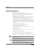
Chapter 3 Installing the Router Pre-Installation Considerations and Requirements Removing the Front Covers from Cisco 12016 Original Series Routers The chassis front covers for the power shelf and upper blower module, upper card cage, lower card cage, and lower blower module are fastened to the chassis by ball studs on the front of the chassis (Figure 3-1).
93279 CDHNT RA DOWN LOOP LA CD TX 0 RX 0 TX 1 RX 2 IER T PK TIV RR AC CA RX E TX RX TX 1 3 E RX RX IER T PK 4 TIV RR AC CA RX TX AL JOR OR ITIC MA MIN CR RX 4 TX TX 2 5 5 T O/L AC RX RX E 6 RX IER T PK TIV RR AC CA RX TX ALARM TX 3 7 RX E 8 IER T PK RX TIV RR AC CA RX TX TX 9 TX L FAI RX LED AB EN 10 L FAI TX LED AB EN RX 0 P/H/F 1 C CS 0 1 ALARM 2 SFC Q OC-3/STM-POS 6DS3–SMB P/H/F RX12DS3–SMB OC-48/STM-16-SCPOS 11 ROUTE PROCESSOR
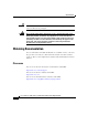
Chapter 3 Installing the Router Pre-Installation Considerations and Requirements Removing the Front Cover from Cisco 12016 Enhanced Series Routers The new cover on the Cisco enhanced series of routers has a two-piece front cover. The covers have release buttons on both sides that give you the flexibility to open it from either the left side or from the right side.
139043 CDHNT RA DOWN LOOP LA CD TX 0 RX 0 TX 1 RX 2 E IER T TIV RR PK AC CA RX TX RX TX 1 3 4 4 RX RX E IER T TIV RR PK AC CA RX TX TX AL JOR OR ITIC MA MIN CR RX RX TX TX 2 5 5 T O/L AC RX RX 6 RX E IER T TIV RR PK AC CA RX TX ALARM TX 3 7 RX 8 RX E IER T TIV RR PK AC CA RX TX TX 9 TX L FAI RX LED AB EN 10 L FAI TX LED AB EN RX 0 P/H/F 1 C CS 0 1 ALARM 2 SFC Q OC-3/STM-POS 6DS3–SMB P/H/F RX12DS3–SMB OC-48/STM-16-SCPOS 11 ROUTE PROCESSOR FA
Chapter 3 Installing the Router Rack-Mounting the Router Chassis Rack-Mounting the Router Chassis The router chassis can be installed in either a front-mounted position or a center-mounted position. Warning • In a front-mounted position, the chassis rack-mounting flanges are secured directly to the rack posts. • In a center-mounted position, an optional set of center-mount brackets are secured to the rack posts and the chassis rack-mounting flanges are then secured to the center-mount brackets.
Chapter 3 Installing the Router Rack-Mounting the Router Chassis Figure 3-3 Verifying Equipment Rack Dimensions Minimum usable aperture 17.7 inches (45.0 cm) 28014 Mounting flanges Hole centerline to hole centerline 18.31 inches ± 0.06 inches (46.5 cm ± 0.15 cm) Installing Center-Mount Brackets—Optional If you plan to install the router in the center-mount position, you must install the center-mount brackets to the rack rails first.
Chapter 3 Installing the Router Rack-Mounting the Router Chassis Step 1 Determine the location in which you want to position the chassis in the rack, and mark holes at the same height on both the left and right rack rails. Step 2 Identify the orientation of the left and right center-mount brackets (Figure 3-4). Figure 3-4 Center-Mount Brackets Threaded holes to chassis 28451 Open holes to rack Left bracket Step 3 Right bracket Install the right center-mount bracket (Figure 3-5). a.
Chapter 3 Installing the Router Rack-Mounting the Router Chassis b. Finger-tighten a second screw in the top hole of the bracket. c. Finger-tighten three more screws in the middle of in the bracket. d. Use a screwdriver to tighten all five screws securely. Step 4 Repeat Step 3 for the left center-mount bracket. Step 5 Use a level to verify that the tops of the two brackets are level, or use a measuring tape to verify that both brackets are the same distance from the top of the rack rails.
Chapter 3 Installing the Router Rack-Mounting the Router Chassis Figure 3-5 Installing a Center-Mount Rack-Mounting Bracket Chassis Rack Bracket Rack 28450 Chassis Bracket rack-mounting rail Threaded hole (chassis secured by screw) Open hole (screw inserted through) Cisco 12016, Cisco 12416, and Cisco 12816 Router Installation and Configuration Guide 3-12 OL-11495-01
Chapter 3 Installing the Router Rack-Mounting the Router Chassis Installing the Chassis Rack-Mounting Platform The rack-mounting platform is installed at the bottom of an empty rack and acts as a permanent support platform for the chassis. It can be installed in either the front-mounted position or the center-mounted position, to match the installed position of the chassis. The platform is adjustable from a minimum height of 5.25 inches (13.34 cm) to a maximum height of 8.00 inches (20.32 cm).
Chapter 3 Installing the Router Rack-Mounting the Router Chassis Repeat these steps to attach a bracket in the same position on the other side of the platform. Align the platform between the rack posts and set it in position so that the sides of the positioning brackets with the oblong holes are flush against the rack-mounting flanges. Step 5 Secure the platform to the rack: a.
Chapter 3 Installing the Router Rack-Mounting the Router Chassis Unpack and Position the Router Unpack the router following the instructions in the Cisco 12016, Cisco 12416, and Cisco 12816 Router Unpacking Instructions that came with the router. Use a safety hand truck to move the router to the location where it is being installed and position it in front of the rack so that the back panel of the chassis faces the rack opening (Figure 3-7).
Chapter 3 Installing the Router Rack-Mounting the Router Chassis Installing the Chassis into the Rack Use the following procedure to install the chassis in the rack. Step 1 Warning Figure 3-8 Rotate the scissor-jack screw counterclockwise slowly and expand the scissor-jack platform to raise the chassis to the required installation height (Figure 3-8). A second person should be holding the chassis to prevent it from tipping while the platform is raised.
Chapter 3 Installing the Router Rack-Mounting the Router Chassis Step 2 Remove the four bolts and chassis anchor clips that secure the base of the chassis to the scissor-jack platform (Figure 3-9).
Chapter 3 Installing the Router Rack-Mounting the Router Chassis Step 3 Grasp the handle on the back panel of the chassis to carefully pull the chassis off of the scissor-jack platform and onto the rack-mounting platform while a second person pushes from the front of the chassis. (See Figure 3-10.) 29192 Figure 3-10 Inserting the Router into the Rack Warning Do not attempt to lift the chassis with the handles on the back and sides of the chassis.
Chapter 3 Installing the Router Rack-Mounting the Router Chassis Step 4 Insert the chassis into the rack until the chassis rack-mounting flanges are flush against the mounting flanges on the rack (or the optional center-mount brackets, if installed). • Note Step 5 The weight of the chassis is now supported by the rack-mounting platform. Remove the scissor-jack platform and set it safely aside.
Chapter 3 Installing the Router Rack-Mounting the Router Chassis Figure 3-11 Chassis Rack-Mounting Hole Groups Chassis mounting holes group E Chassis mounting holes group D Chassis mounting holes group C Chassis mounting holes group B 26864 Chassis mounting holes group A Cisco 12016, Cisco 12416, and Cisco 12816 Router Installation and Configuration Guide 3-20 OL-11495-01
Chapter 3 Installing the Router Supplemental Bonding and Grounding Connections Supplemental Bonding and Grounding Connections Before you connect power to the router, or power on the router for the first time, we recommend that you connect the central office ground system or new equipment building system (NEBS) to the supplemental bonding and grounding points on the router.
Chapter 3 Installing the Router Supplemental Bonding and Grounding Connections Connecting to the Front Grounding Receptacle Use the following procedure to connect the supplemental grounding cable to front grounding receptacle. Step 1 Loosen the two captive screws on each side of the air filter door and pivot the door open (Figure 3-12).
Chapter 3 Installing the Router Supplemental Bonding and Grounding Connections Step 2 Attach the grounding cable to the chassis (Figure 3-13): a. Insert two M6 bolts through the grounding holes in the chassis. b. Place the cable lug over the bolts and secure with the locking washers and nuts.
Chapter 3 Installing the Router Supplemental Bonding and Grounding Connections Connecting to the Top Rear Receptacle Use the following procedure to connect the supplemental grounding cable to top rear grounding receptacle. Step 1 Attach the grounding cable to the chassis (Figure 3-14): a. Insert two M6 bolts through the grounding holes in the chassis. b. Place the cable lug over the bolts and secure with the locking washers and nuts.
Chapter 3 Installing the Router Attaching the Vertical Cable-Management Trough Attaching the Vertical Cable-Management Trough Refer to Figure 3-15 and use the following procedure to attach the vertical cable-management trough. Step 1 Position the trough so that the access gate opens toward the front of the chassis. Step 2 Align the top screw holes on the inside panel of the trough with the chassis standoffs. Step 3 Hand tighten two screws into the holes to hold the trough in place.
28746 CDHNT RA DOWN LOOP LA CD TX 0 RX 0 TX 1 RX 2 E IER TIV RR PK AC CA RX TX T RX TX 1 3 4 RX RX T E IER TIV RR PK AC CA RX TX 4 AL JOR OR ITIC MA MIN CR RX TX TX TX 2 5 5 T O/L AC RX RX 6 T RX E IER TIV RR PK AC CA RX TX ALARM TX 3 7 RX 8 RX T E IER TIV RR PK AC CA RX TX TX 9 L TX FAI RX LED AB EN 10 L FAI TX LED AB EN RX 0 P/H/F 1 CS C 0 1 ALARM 2 C SF Q OC-3/STM-POS 6DS3–SMB P/H/F RX12DS3–SMB OC-48/STM-16-SCPOS 11 ROUTE PROCES
Chapter 3 Installing the Router Connecting Line Card Network Interface Cables Connecting Line Card Network Interface Cables This section describes how to route the network interface cables through the router cable-management system and attach the network interface cables to the line card ports. This procedure uses an 8-port fiber-optic Fast Ethernet card as an example to describe how to attach a network interface cable to a line card port and route the cable through the cable-management system.
Chapter 3 Installing the Router Connecting Line Card Network Interface Cables Step 5 Repeat Steps 3 through 5 for each additional cable connection to that line card.
Chapter 3 Installing the Router Connecting Line Card Network Interface Cables Step 6 Insert all cables into their assigned ports. Step 7 Place several evenly spaced velcro straps through slots on the cable-management bracket (Figure 3-17a). Step 8 Route the cables alongside the cable-management bracket and secure them with the velcro straps as appropriate (Figure 3-17b).
Chapter 3 Installing the Router Connecting Line Card Network Interface Cables Figure 3-17 Current Style Cable Management Bracket a b 0 0 AC T CA IVE R RX RIE PK R T 1 AC T CA IVE R RX RIE PK R T 2 AC T CA IVE R RX RIE PK R T 3 Velcro strap AC T CA IVE R RX RIE PK R T Line card cable-management bracket Network interface cable 1 AC T CA IVE R RX RIE PK R T 2 AC T CA IVE R RX RIE PK R T 3 AC T CA IVE R RX RIE PK R T AC T CA IVE R RX RIE PK R T 53228 Q OC-3/STM-POS Q OC-3/STM-POS Cisc
Chapter 3 Installing the Router Connecting GRP Route Processor Cables Connecting GRP Route Processor Cables This section describes how to connect cables to the console, auxiliary, and Ethernet ports on the GRP. The console and auxiliary ports are both asynchronous serial ports; any devices connected to these ports must be capable of asynchronous transmission. For example, most modems are asynchronous devices. Figure 3-18 shows an example of a data terminal and modem connections.
Chapter 3 Installing the Router Connecting GRP Route Processor Cables Note To comply with Telcordia GR-1089 NEBS standard for electromagnetic compatibility and safety, connect all console, auxiliary, and Ethernet interfaces only to intrabuilding or nonexposed wiring or cabling. The intrabuilding cable must be shielded and the shield must be grounded at both ends.
Chapter 3 Installing the Router Connecting GRP Route Processor Cables Connecting to the GRP Auxiliary Port The auxiliary port on the GRP is an EIA/TIA-232 DTE DB-25 plug for connecting a modem or other DCE device (such as a channel service unit/data service unit (CSU/DSU) or another router) to this router. See the “GRP Auxiliary and Console Port Connections” section on page 2-26 for more information. Use the following procedure to connect an asynchronous serial device to the GRP auxiliary port.
Chapter 3 Installing the Router Connecting GRP Route Processor Cables LEDs on the front panel indicate which Ethernet receptacle is active when the GRP is operating. See “GRP Ethernet Port Connections” section on page 2-29 for additional information about GRP Ethernet ports. Caution Ethernet ports are primarily used as a Telnet port into the Cisco 12000 series router, and for booting or accessing Cisco IOS software images over a network to which an Ethernet port is directly connected.
Chapter 3 Installing the Router Connecting GRP Route Processor Cables RJ-45 Connection Use the following procedure to connect an Ethernet cable to the RJ-45 receptacle. Step 1 Plug the cable directly into the RJ-45 receptacle. Step 2 Connect the network end of your RJ-45 cable to your transceiver, switch, hub, repeater, DTE, or other external equipment. Note The Ethernet interfaces on the GRP are endstation devices only, not repeaters.
Chapter 3 Installing the Router Connecting PRP Route Processor Cables Connecting PRP Route Processor Cables This section describes how to connect cables to the console, auxiliary, and Ethernet ports on the PRP. The console and auxiliary ports are both asynchronous serial ports; any devices connected to these ports must be capable of asynchronous transmission. For example, most modems are asynchronous devices. Figure 3-20 shows an example of a data terminal and modem connections.
Chapter 3 Installing the Router Connecting PRP Route Processor Cables Note RP cables are not available from Cisco, but are available from any commercial cable vendor. Note To comply with Telcordia GR-1089 NEBS standard for electromagnetic compatibility and safety, connect all console, auxiliary, Ethernet, and BITS (PRP2) interfaces only to intrabuilding or nonexposed wiring or cabling. The intrabuilding cable must be shielded and the shield must be grounded at both ends.
Chapter 3 Installing the Router Connecting PRP Route Processor Cables Connecting to the PRP Auxiliary Port The auxiliary port on the PRP is a DTE, RJ-45 receptacle for connecting a modem or other DCE device (such as a CSU/DSU or another router) to the router. The asynchronous auxiliary port supports hardware flow control and modem control. See the “PRP Auxiliary and Console Port Connection Guidelines” section on page 2-36 for additional information about the auxiliary port.
Chapter 3 Installing the Router Connecting PRP Route Processor Cables Note Caution RJ-45 cables are not available from Cisco Systems; they are available from outside commercial cable vendors. Use cables that comply with EIA/TIA-568 standards. Ethernet ports are primarily used as a Telnet port into the Cisco 12000 series router, and for booting or accessing Cisco IOS software images over a network to which an Ethernet port is directly connected.
Chapter 3 Installing the Router Connecting an Alarm Card Cable Connecting an Alarm Card Cable Each router alarm card has one 25-pin Dsub connector, labeled Alarm (Figure 3-21).
Chapter 3 Installing the Router Connecting Power to the Power Shelf Caution Note Only safety extra-low voltage (SELV) circuits can be connected to the alarm connector. Maximum rating for the alarm circuit is 2 A, 50 VA. To comply with Telcordia GR-1089 NEBS standard for electromagnetic compatibility and safety, you must use a shielded cable when connecting to the external alarm ports on the alarm card.
Chapter 3 Installing the Router Connecting Power to the Power Shelf Step 1 Connect each AC power cord to the back panel of the power shelf and secure them in place with their retention clips (Figure 3-22). Figure 3-22 Connecting AC Power Cords 28019 Power cord retention clip Step 2 Plug each power supply cable into its AC outlet. Connecting Power to the DC-Input Power Shelf This section contains the procedures to connect the DC source power cables to a DC-powered router.
Chapter 3 Installing the Router Connecting Power to the Power Shelf Because there is no color code standard for source DC wiring, you must be sure that power source cables are connected to the power shelf with the proper positive (+) and negative (–) polarity: • In some cases, the source DC cable leads might have a positive (+) or a negative (–) label. This is a relatively safe indication of the polarity, but you must verify the polarity by measuring the voltage between the DC cable leads.
Chapter 3 Installing the Router Connecting Power to the Power Shelf Figure 3-23 DC-Input Terminal Connections on the DC-Input Power Shelf B1 B2+ B2- B1+ B1- Ground 27964 A1- A1+ A2- A2+ Cover with slotted screw hole; fastens to standoff in middle of cable connection area Cisco 12016, Cisco 12416, and Cisco 12816 Router Installation and Configuration Guide 3-44 OL-11495-01
Chapter 3 Installing the Router Connecting Power to the Power Shelf Step 2 Connect the ground and each pair of power cables to the DC-input terminal studs as follows (Figure 3-24): Warning When reconnecting source DC power cables, always connect the ground cable first. a. Connect the ground cable to the ground terminal studs. Beginning with terminal studs B2: b. Connect the positive cable to the positive (+) terminal studs. For example: B2+. c.
Chapter 3 Installing the Router Connecting Power to the Power Shelf Step 3 Reinstall the power cable cover (Figure 3-25). Figure 3-25 Reinstalling the Source DC Power Cable Cover + – Ground 27219 Cover standoff Cover with slotted screw hole; fastens to standoff in middle of cable connection area.
Chapter 3 Installing the Router Installing the Front Covers of Cisco 12016 Original Series Routers Installing the Front Covers of Cisco 12016 Original Series Routers The chassis front covers for the power shelf and upper blower module, upper card cage, lower card cage, and lower blower module are fastened to the chassis by ball studs on the front of the chassis (Figure 3-26).
93279 CDHNT RA DOWN LOOP LA CD TX 0 RX 0 TX 1 RX 2 IER T PK TIV RR AC CA RX E TX RX TX 1 3 E RX RX IER T PK 4 TIV RR AC CA RX TX 4 AL JOR OR ITIC MA MIN CR RX TX TX TX 2 5 5 T O/L AC RX RX E 6 RX IER T PK TIV RR AC CA RX TX ALARM TX 3 7 RX E 8 IER T PK RX TIV RR AC CA RX TX TX 9 TX L FAI RX LED AB EN 10 L FAI TX LED AB EN RX 0 P/H/F 1 C CS 0 1 ALARM 2 SFC Q OC-3/STM-POS 6DS3–SMB P/H/F RX12DS3–SMB OC-48/STM-16-SCPOS 11 ROUTE PROCESS
Chapter 3 Installing the Router Installing the Front Cover of Cisco 12010 Enhanced Series Routers 1 Ball stud 2 Ball stud clip Installing the Front Cover of Cisco 12010 Enhanced Series Routers Refer to Figure 3-27 and use the following procedure to install the front cover for the Cisco 12010 enhanced series routers. Step 1 Align the hinges on each side of the cover with the hinge connectors on each side of the chassis (see blowout in Figure 3-27).
139043 CDHNT RA DOWN LOOP LA CD TX 0 RX 0 TX 1 RX 2 E IER T TIV RR PK AC CA RX TX RX TX 1 3 4 4 RX RX E IER T TIV RR PK AC CA RX TX TX AL JOR OR ITIC MA MIN CR RX RX E IER T TIV RR PK CA RX TX TX 2 5 5 T O/L AC RX RX 6 RX E IER T TIV RR PK AC CA RX TX ALARM TX 3 7 RX 8 RX E IER T TIV RR PK AC CA RX TX TX 9 TX L FAI RX LED AB EN 10 L FAI TX LED AB EN RX 0 P/H/F 1 C CS 0 1 ALARM 2 SFC Q OC-3/STM-POS 6DS3–SMB P/H/F RX12DS3–SMB OC-48/STM-16-SCPOS
Chapter 3 Installing the Router Installing the Front Cover of Cisco 12010 Enhanced Series Routers This completes the hardware installation procedures for Cisco 12016, Cisco 12416, and Cisco 12816 routers. Proceed to the next chapter to perform the initial router startup and basic configuration.
Chapter 3 Installing the Router Installing the Front Cover of Cisco 12010 Enhanced Series Routers Cisco 12016, Cisco 12416, and Cisco 12816 Router Installation and Configuration Guide 3-52 OL-11495-01
C H A P T E R 4 System Startup and Basic Configuration The system startup process and a procedure for performing a basic configuration of your Cisco 12016, Cisco 12416, or Cisco 12816 router is presented in the following sections: • Sources of Cisco IOS Software, page 4-2 • Preconfiguration Requirements, page 4-2 • Boot Process Overview, page 4-3 • Powering On the Router and Observing the Boot Process, page 4-4 • Manually Booting the System, page 4-11 • Configuring the Router, page 4-14 • Cis
Chapter 4 System Startup and Basic Configuration Sources of Cisco IOS Software This chapter provides you with the information to configure your system so that it can access the network or enable other hosts in the network to access your system remotely by means of a Telnet connection. Detailed configuration procedures are beyond the scope of this document, but you can find more information in the “Post-Installation Procedures” section on page 4-63.
Chapter 4 System Startup and Basic Configuration Boot Process Overview • Note • A terminal device is connected to the console port on the RP, powered on, and configured for 9600 bps, 8 data bits, no parity, and 2 stop bits (9600, 8N2). You must connect a terminal to the RP to perform the initial configuration of the router. The flash memory card that shipped with your router is installed in slot 0 of the RP.
Chapter 4 System Startup and Basic Configuration Powering On the Router and Observing the Boot Process 7. When the Cisco IOS software boots, it polls all other cards in the system, powers them on, and loads the Cisco IOS software they require. 8. The RP waits for all other cards to finish their boot processes.
Chapter 4 System Startup and Basic Configuration Powering On the Router and Observing the Boot Process Step 4 Observe the RP alphanumeric LED displays during the RP boot process (Figure 4-1). Figure 4-1 RP Alphanumeric LED Displays PROCESSOR Upper alphanumeric LED display (four digits) H10780 Lower alphanumeric LED display (four digits) Each 4-digit display shows part of a 2-line system message.
Chapter 4 System Startup and Basic Configuration Powering On the Router and Observing the Boot Process Table 4-1 RP Alphanumeric LED Display Sequence Examples (continued) LED Display1 Meaning PRI RP The RP is enabled and is recognized as the system primary RP. A valid RP Cisco IOS Cisco IOS image is running. software SEC RP The RP is enabled and is recognized as the system secondary RP. A valid Cisco IOS image is running. Source RP Cisco IOS software 1.
Chapter 4 System Startup and Basic Configuration Powering On the Router and Observing the Boot Process Figure 4-2 GRP LEDs—Partial Front Panel View T EC EJ -1 OT SL -0 OT SL T SE RE X AU K LIN LL CO TX 5 -4 RJ H10762 RX I MI PRP Ethernet Ports and LEDs—Partial Front Panel View K TX EN TX PRIMARY 70693 PRIMARY LIN K EN SL RX RX ETH 1 S OT LOT -0 -1 ETH 0 LIN Figure 4-3 Cisco 12016, Cisco 12416, and Cisco 12816 Router Installation and Configuration Guide OL-11495-01 4-7
Chapter 4 System Startup and Basic Configuration Powering On the Router and Observing the Boot Process Step 6 During the line card boot process, observe the alphanumeric LED displays on each line card (Figure 4-4). Note The line card boot process occurs immediately after the RP boot process. The system attempts to boot identical line cards in parallel. Further, the system boots line cards as soon as they are powered on and become available.
Chapter 4 System Startup and Basic Configuration Powering On the Router and Observing the Boot Process Table 4-2 Line Card Alphanumeric LED Display Sequence Examples (continued) LED Display1 Meaning Source ROMI GET The ROM image is being loaded into line card memory. RP Cisco IOS software FABL WAIT The line card is waiting for the fabric downloader to load.3 RP Cisco IOS software FABL DNLD The fabric downloader is being loaded into line card memory.
Chapter 4 System Startup and Basic Configuration Powering On the Router and Observing the Boot Process Step 7 The router automatically boots using the default image (if a flash memory card containing a valid Cisco IOS software image is inserted in slot 0 and the software configuration register is set to 0x0102).
Chapter 4 System Startup and Basic Configuration Manually Booting the System You do not need to configure the network interfaces immediately, but you cannot connect to a network until you configure the interfaces for operation in your network environment. For configuration information, see the “Configuring the Router” section on page 4-14. Note The interface-specific LEDs on the line cards may not power on until you configure the line card interfaces.
Chapter 4 System Startup and Basic Configuration Manually Booting the System Locating a Valid Cisco IOS Software Image Use the following procedure to locate a Cisco IOS software image to manually boot the router from the ROM monitor prompt (rommon>). Step 1 Enter the ROM monitor mode dir bootflash command to examine the contents of the onboard flash memory in NVRAM on the RP. rommon 1> dir bootflash: File size 3277967 bytes (0x32048f) rommon 2> Step 2 Checksum 0x6b331e30 File name gsr-p-mz.120-7.4.
Chapter 4 System Startup and Basic Configuration Manually Booting the System Caution Use the boot flash command with care. Make sure that the flash memory card inserted in slot 0 contains a valid Cisco IOS software image; otherwise, you could instruct the system to boot an invalid image from the flash memory card. Before entering a boot command, always enter the dir slotn: command to examine the contents of a flash memory card. Table 4-3 Boot Commands Command Purpose boot (No argument.
Chapter 4 System Startup and Basic Configuration Configuring the Router Note If you did not change the configuration register setting, the next reload will revert to the default configuration register setting (0x0102). This setting causes the system to boot Cisco IOS software from a flash memory card inserted in slot 0 the next time you boot the router. See the “Configuring the Software Configuration Register” section on page 4-31 for additional information.
Chapter 4 System Startup and Basic Configuration Cisco IOS User Interface You can use the method that suits your operating style and your knowledge of network configuration requirements. Whether you use the setup command facility or global configuration mode to configure the router to operate in your networking environment, be sure you know the: • Interfaces the router has. • Protocols the router is routing. • Network addresses for the protocols being configured.
Chapter 4 System Startup and Basic Configuration Cisco IOS User Interface The configuration modes allow you to make changes to the running configuration file. If you save the configuration, the commands are stored and persist across router reboots. In order to access the various configuration modes, you must start from global configuration mode. From global configuration mode, you can enter interface configuration mode, subinterface configuration mode, and a variety of protocol-specific modes.
Chapter 4 System Startup and Basic Configuration Cisco IOS User Interface The following example shows the change from user EXEC mode to privileged EXEC mode. Router> enable password: Router# For information about using passwords, see the “Configuring Passwords” section on page 4-23. Global Configuration Mode Global configuration commands: • Apply to features that affect the system as a whole, rather than just one protocol or interface.
Chapter 4 System Startup and Basic Configuration Cisco IOS User Interface Subinterface Configuration Mode Use subinterface configuration mode to configure multiple virtual interfaces (called subinterfaces) on a single physical interface. Subinterfaces appear to be distinct physical interfaces to the various protocols. For detailed information on how to configure subinterfaces, refer to the appropriate module for a specific protocol in the Cisco IOS software documentation.
Chapter 4 System Startup and Basic Configuration Cisco IOS User Interface To use the setup command to change a configuration: 1. You must toggle through each system configuration dialog prompt until you come to the item that you intend to change. – To accept default settings for items that you do not want to change, press the Return key. – To return to the privileged EXEC prompt without making changes and toggling through each system configuration dialog prompt, press Ctrl-C.
Chapter 4 System Startup and Basic Configuration Cisco IOS User Interface to configure each interface of the system. Would you like to enter basic management setup? [yes/no]: Yes Configuring global parameters: Enter host name [Router]: Milo The enable secret is a password used to protect access to privileged EXEC and configuration modes. This password, after entered, becomes encrypted in the configuration.
Chapter 4 System Startup and Basic Configuration Cisco IOS User Interface line vty 0 4 password bambam no snmp server ! no ip routing ! interface Ethernet0 no shutdown ip address 172.16.72.2 255.255.255.0 ! interface POS1/0 shutdown no ip address ! interface SDCC1/0 shutdown no ip address . . . interface POS15/0 shutdown no ip address ! interface SDCC15/0 shutdown no ip address ! end [0] Go to the IOS command prompt without saving this script. [1] Return back to the setup without saving this config.
Chapter 4 System Startup and Basic Configuration Cisco IOS User Interface For example, during the configuration of a POS interface, (using the setup facility initial router startup), the script appears as the following example as you respond to queries: Configuring interface POS1/0: Is this interface in use?: yes Configure IP on this interface?: yes In this example, the script does not display default or current parameters in square brackets [ ], because you entered the setup facility automatically at s
Chapter 4 System Startup and Basic Configuration Cisco IOS User Interface Configuring Host Name The host name you configure your router with must: • Follow the rules for ARPANET host names. • Start with a letter, end with a letter or digit, and have as interior characters only letters, digits, and hyphens. • Consist of 63 or fewer characters. For more information, refer to RFC 1035, “Domain Names—Implementation and Specifications.
Chapter 4 System Startup and Basic Configuration Cisco IOS User Interface In either case, you cannot use a number as the first character. Spaces, however, are valid password characters. For example, two words is a valid password. Leading spaces are ignored, but trailing spaces are recognized. Note Make a note of all passwords you set and store that information in a secure location for future reference.
Chapter 4 System Startup and Basic Configuration Cisco IOS User Interface The following configuration dialog example shows how to configure the system for an Ethernet interface that uses the IP network layer protocol. Note The Ethernet interface does not support external routing functions. Configuring interface Ethernet0: Is this interface in use?: yes Configure IP on this interface?: yes IP address for this interface: 3.3.1.1 Number of bits in subnet field: 8 Class A network is 3.0.0.
Chapter 4 System Startup and Basic Configuration Cisco IOS User Interface The following example shows how to configure an ATM line card to use IP. Configuring interface parameters: Configuring interface ATM1/0: Is this interface in use?: yes Configure IP on this interface?: yes IP address for this interface: 1.1.1.2 Number of bits in subnet field: 0 Class A network is 1.0.0.0, 0 subnet bits; mask is 255.0.0.
Chapter 4 System Startup and Basic Configuration Cisco IOS User Interface System image file is "tftp://xxx.xxx.xxx.xxx/directory/ghall/gsr-p-mz" cisco 12410/GRP (R5000) processor (revision 0x05) with 262144K bytes of memory. R5000 CPU at 200Mhz, Implementation 35, Rev 2.1, 512KB L2 Cache Last reset from power-on 1 Route Processor Card 2 Clock Scheduler Cards 5 Switch Fabric Cards 2 OC48 POS controllers (2 POS). 1 four-port OC48 POS controller (1 POS). 1 Ethernet/IEEE 802.
Chapter 4 System Startup and Basic Configuration Cisco IOS User Interface Step 3 Enter the configure terminal command to enter global configuration mode. Milo# configure terminal Enter configuration commands, one per line. End with CNTL/Z. Milo(config)# Step 4 Enter the interface type slot/port command to enter interface configuration mode. Milo(config)# interface type slot/port Milo(config-if)# Step 5 Enter the copy running-config startup-config command to save your configuration settings.
Chapter 4 System Startup and Basic Configuration Cisco IOS User Interface clock source internal ! interface POS1/1 no ip address no ip route-cache cef no ip route-cache shutdown crc 32 ! interface POS1/2 no ip address no ip route-cache cef no ip route-cache shutdown crc 32 ! interface POS1/3 no ip address no ip route-cache cef no ip route-cache shutdown crc 32 Saving the Running Configuration Settings to NVRAM The copy running-config startup-config command saves the configuration settings that you create
Chapter 4 System Startup and Basic Configuration Cisco IOS User Interface Viewing the Running Configuration Settings You can use the show startup-config command to view the current configuration settings stored in NVRAM. The following example shows the type of information generated by this command. Milo# show startup-config Using 5560 out of 520184 bytes ! version 12.
Chapter 4 System Startup and Basic Configuration Configuring the Software Configuration Register ! map-list atm1 ip 10.1.1.1 atm-vc ip 10.1.1.3 atm-vc ip 10.1.1.4 atm-vc ip 10.0.0.1 atm-vc ip 10.0.0.5 atm-vc ip 10.0.0.6 atm-vc no logging trap ! ! line con 0 exec-timeout 0 0 line aux 0 line vty 0 4 password bambam login ! end 1 2 4 3 10 11 Configuring the Software Configuration Register The software configuration register is a 16-bit register in NVRAM that defines specific system parameters.
Chapter 4 System Startup and Basic Configuration Configuring the Software Configuration Register • Read boot system commands from the configuration file stored in NVRAM. Table 4-4 defines software configuration register bits. Caution To avoid confusion and possibly halting the system, remember that valid software configuration register values may be combinations of settings, rather than the individual settings listed in Table 4-4.
Chapter 4 System Startup and Basic Configuration Configuring the Software Configuration Register The boot field (Table 4-5) defines a source for booting a default Cisco IOS software image required to run the router. The content of the boot field is specified as a binary number. Table 4-5 Note Boot Field—Software Configuration Register Boot Field Meaning at Power-On 00 System remains at the ROM monitor prompt (rommon>), awaiting a user command to boot the system manually.
Chapter 4 System Startup and Basic Configuration Configuring the Software Configuration Register Depending on the boot field setting, the system ignores boot instructions in the system configuration file and performs one of the following operations: • When the boot field is set to 0—You must boot the operating system manually by entering the boot command at the ROM monitor prompt (rommon>). You can enter the boot command with or without arguments.
Chapter 4 System Startup and Basic Configuration Configuring the Software Configuration Register For example, the filename formation process may yield a range of typical filenames like the following: cisco2-grp . . . cisco17-grp The system uses one of the filenames in this range to boot a default system image stored on a network TFTP server.
Chapter 4 System Startup and Basic Configuration Configuring the Software Configuration Register Step 3 Set the contents of the software configuration register by entering the config-register value command, where value is a hexadecimal number preceded by 0x. Milo(config)# config-register 0xvalue Note Step 4 Consult the hexadecimal column in Table 4-4 on page 4-32 for the possible settings to enter as the 4-bit value parameter. Press Ctrl-Z to exit global configuration mode.
Chapter 4 System Startup and Basic Configuration Configuring the Software Configuration Register Low-Order Bits in the Software Configuration Register This section provides detail about of the low-order bits in the software configuration register and how they interact during the router boot process. As described in the “Setting Software Configuration Settings” section on page 4-33, the boot field setting determines the source of the Cisco IOS software image used to boot the router.
Chapter 4 System Startup and Basic Configuration Configuring the Software Configuration Register Note If a bootable Cisco IOS software image exists in a flash memory card installed in slot 0 or slot 1, the configuration register setting is overridden, and the bootable Cisco IOS software image is booted instead of the default TFTP-bootable Cisco IOS software image (cisco2-grp through cisco17-grp or cisco2-prp through cisco17-prp).
Chapter 4 System Startup and Basic Configuration Configuring the Software Configuration Register High-Order Bits in the Software Configuration Register This section describes the significance of high-order bits in the software configuration register. • Bit 8 of the software configuration register controls the console Break key. – Setting bit 8 causes the system to ignore the console Break key (factory default).
Chapter 4 System Startup and Basic Configuration Configuring the Software Configuration Register • Bits 11 and 12 of the software configuration register determine the data transmission rate of the console terminal. Table 4-8 shows the bit settings for four data transmission rates. Table 4-8 System Console Terminal Data Transmission Rate Settings Bit 12 Bit 11 Data Transmission Rate (bps) 0 0 96001 0 1 4800 1 0 1200 1 1 2400 1. Default.
Chapter 4 System Startup and Basic Configuration Recovering a Lost Password Recovering a Lost Password Use the following procedure to recover a lost password. Note This procedure does not work for password recovery if the enable password is encrypted—you must reconfigure the system before attempting a reboot (see the “Configuring the Router” section on page 4-14). Step 1 Enter the show version command at the privileged EXEC mode prompt to display the existing software configuration register value.
Chapter 4 System Startup and Basic Configuration Recovering a Lost Password enable enable enable enable enable change change “use net in IP bcast address”? y/n [n]: “load rom after netbootfails”? y/n [n]: “use all zero broadcast”? y/n [n]: “break/abort has effect?” y/n [n]: “ignore system config info?” [n]: y console baud rate? y/n [n]: boot characteristics? y/n [n] Configuration Summary enabled are: console baud: 9600 boot: image specified by the boot system command or default to: cisco2-prp do you wi
Chapter 4 System Startup and Basic Configuration Recovering a Lost Password Step 7 Enter the enable command and password (if prompted). Milo> enable Password: Milo# Step 8 Enter the show startup-config command to display the enabled password in the configuration file. Milo# show startup-config . . . password bambam Step 9 Enter the configure terminal command to enter global configuration mode: Milo# configure terminal Enter configuration commands, one per line. End with CNTL/Z.
Chapter 4 System Startup and Basic Configuration Using RP Flash Memory Cards Using RP Flash Memory Cards This section describes how to use RP flash memory cards and includes information on the following topics: • Installing and Removing a Flash Memory Card, page 4-44 • Formatting a New Flash Memory Card, page 4-47 • Specifying a Cisco IOS Software Image to Boot the System, page 4-48 • Flash Memory Commands, page 4-49 • Booting from Flash Memory, page 4-52 • Copying Image Files to or From Flash
Chapter 4 System Startup and Basic Configuration Using RP Flash Memory Cards Step 3 Caution Step 4 Insert the card into the appropriate slot until the card completely seats in the connector and the ejector button pops out (see Figure 4-5b). The flash memory card is keyed for proper insertion. The ejector button does not pop out unless the card is inserted correctly. Part of the card remains outside of the slot even when the card is properly seated.
Chapter 4 System Startup and Basic Configuration Using RP Flash Memory Cards Figure 4-5 Installing and Removing a Flash Memory Card a T EC EJ -1 OT SL -0 OT SL b T SE X AU RE T EC EJ c -1 OT SL -0 OT SL T SE X AU RE T EC EJ -1 OT SL -0 OT SL H10703 T SE X AU RE Cisco 12016, Cisco 12416, and Cisco 12816 Router Installation and Configuration Guide 4-46 OL-11495-01
Chapter 4 System Startup and Basic Configuration Using RP Flash Memory Cards Formatting a New Flash Memory Card The flash memory card that shipped with your router contains the default Cisco IOS software image you need to boot your router. If you require a new flash memory card to copy images or backup configuration files, you must first format the card. Note Use only Type I or Type II flash memory cards. Use the following procedure to format a new flash memory card.
Chapter 4 System Startup and Basic Configuration Using RP Flash Memory Cards Specifying a Cisco IOS Software Image to Boot the System Use the procedure in this section to identify a specific Cisco IOS software image (new.image in this example) that you want to make bootable from a flash memory card. The software configuration register must be set to 0x2102 to boot the image from the flash memory card.
Chapter 4 System Startup and Basic Configuration Using RP Flash Memory Cards Flash Memory Commands This section describes console commands that you can use to access the different types of flash memories. Enter these commands from the privileged EXEC mode prompt. pwd Command To determine whether the present device you are accessing is the onboard flash SIMM on the RP or a PCMCIA flash memory card, use the pwd command. This example shows how to access a flash memory card in slot 0 of the RP.
Chapter 4 System Startup and Basic Configuration Using RP Flash Memory Cards dir Command To list the directory contents of the flash memory in use, enter the dir [device-name] command. Where device-name can be slot0:, slot1:, or bootflash:. The following example shows the contents of the flash memory card in slot 0.
Chapter 4 System Startup and Basic Configuration Using RP Flash Memory Cards squeeze Command The squeeze command permanently removes deleted files from flash memory and makes all other (undeleted) files contiguous to conserve storage space. To permanently remove deleted files from a flash memory directory, but leave the other files intact, enter the squeeze device-name command. • Where device-name can be slot0:, slot1:, or bootflash:.
Chapter 4 System Startup and Basic Configuration Using RP Flash Memory Cards Booting from Flash Memory To boot from flash memory, the boot field in the software configuration register (bits 3 through 0) must be set to a value between 2 and 15 (see the “Configuring the Software Configuration Register” section on page 4-31). Use the following command to enable booting from flash memory.
Chapter 4 System Startup and Basic Configuration Using RP Flash Memory Cards Use the following command to copy a file to flash memory. Milo# copy tftp:filename [bootflash:|slot0:|slot1:] filename Where: • tftp:filename specifies the source and name of the file to be copied. • [bootflash: | slot0: | slot1:] filename specifies the destination flash device and name of the file.
Chapter 4 System Startup and Basic Configuration Using RP Flash Memory Cards CCCCCCCCCCCCCCCCCCCCCCCCCCCCCCCCCCCCCCCCCCCCCCCCCCCCCCCCCCCCCCCCCCCCCC CC Milo# In this example: • The exclamation points (!!!) appear as the source file is being downloaded to the destination device. • The C characters indicate that a cyclic redundancy check (CRC) is being calculated during the downloading process.
Chapter 4 System Startup and Basic Configuration Using RP Flash Memory Cards Use the following procedure to copy a bootable image into the flash memory card: Step 1 Boot the router. Step 2 Enter the enable command and password (if prompted). Milo> enable Password: Milo# Step 3 Enter the copy command to copy the file (new.image in this example) from the server to the flash memory card in slot 0. Milo# copy tftp:new.image slot0:new.
Chapter 4 System Startup and Basic Configuration Using RP Flash Memory Cards Copying Cisco IOS Software Images Between Flash Memory Cards This procedure describes how to copy a later Cisco IOS software image from one flash memory card to another flash memory card containing an earlier Cisco IOS software image. In this example, the following filenames apply: • image.new—The new image on the flash memory card located in slot 1. • image.old—The old image on the flash memory card in slot 0. • image.
Chapter 4 System Startup and Basic Configuration Using RP Flash Memory Cards Step 3 Enter the following commands to designate the file named image.new in the memory card in slot 0 as the new default system image for boot purposes: Milo# configure terminal Milo(config)# no boot system Milo(config)# boot system flash slot0:image.new Ctrl-Z Milo# copy running-config startup-config Milo# reload When the system reloads, it boots the image.new file from the memory card in slot 0.
Chapter 4 System Startup and Basic Configuration Using RP Flash Memory Cards Copying the Startup Configuration File from NVRAM to a Flash Memory Card Use the following procedure to copy a configuration file from NVRAM to a flash memory card. Step 1 Enter the show bootvar command to display the current setting for the environmental CONFIG_FILE variable. The environmental CONFIG_FILE variable must point to NVRAM (system default). Note Milo# show bootvar . . .
Chapter 4 System Startup and Basic Configuration Using RP Flash Memory Cards Milo# copy startup-config slot0:myfile2 20575008 bytes available on device slot0, proceed? [confirm] Address or name of remote host [1.1.1.1]? Loading new.image from 1.1.1.
Chapter 4 System Startup and Basic Configuration Using RP Flash Memory Cards Copying the Running Configuration File from DRAM to a Flash Memory Card Use the following procedure to copy the running configuration file from DRAM on the RP to a flash memory card. Step 1 Enter the copy command in the following form: copy running-config [slot0:|slot1:]filename Where: • running-config is the source configuration file in DRAM.
Chapter 4 System Startup and Basic Configuration Using RP Flash Memory Cards Step 2 Enter the dir command to further verify that the configuration file is copied correctly to the memory card in slot 0: Milo# dir slot0: -#- -length- -----date/time-----1 5200084 May 10 1997 19:24:12 3 1215 May 10 1997 20:30:52 4 6176844 May 10 1997 23:04:10 5 1186 May 10 1997 16:56:50 name gsr-p-mz.112-8 myfile1 gsr-p-mz.112-8.
Chapter 4 System Startup and Basic Configuration Using RP Flash Memory Cards Booting a New Cisco IOS Software Image from a Flash Memory Card Use the following procedure to boot a new image from a flash memory card in slot 0 or slot 1 (this example uses slot 0). Step 1 Insert the flash memory card with the new image in slot 0. Step 2 Enter the following commands to designate the file named image.
Chapter 4 System Startup and Basic Configuration Post-Installation Procedures Post-Installation Procedures After you install the router hardware, check all external connections, turn on the system power, allow the system to boot up, and minimally configure the system, you may need to perform additional configuration tasks. The Cisco IOS software running your router contains extensive features and functionality.
Chapter 4 System Startup and Basic Configuration Post-Installation Procedures Cisco 12016, Cisco 12416, and Cisco 12816 Router Installation and Configuration Guide 4-64 OL-11495-01
C H A P T E R 5 Troubleshooting the Installation This chapter contains general troubleshooting information to help isolate the cause of difficulties you might encounter during the installation and initial startup of the system. The procedures in this chapter assume that you are troubleshooting the initial startup of the router, as described in the Powering On the Router and Observing the Boot Process, page 4-4, and that the system is running the original configuration.
Chapter 5 Troubleshooting the Installation Troubleshooting Overview Troubleshooting Overview This section describes the methods used in troubleshooting the router. The troubleshooting methods are organized according to the major subsystems in the router. If you are unable to solve a problem on your own, you can contact a Cisco customer service representative for assistance.
Chapter 5 Troubleshooting the Installation Troubleshooting Overview • Chassis backplane power distribution. –48 VDC power from the power supplies is transferred to the chassis backplane. The –48 VDC is distributed to all of the cards through the backplane connectors. The blower module receives power from the chassis backplane through a wiring harness and passes MBus data back to the chassis backplane. • Processor subsystem—Includes redundant RPs, line cards, switch fabrics, and two alarm cards.
Chapter 5 Troubleshooting the Installation Troubleshooting Overview Identifying Startup Issues Table 5-1 shows the contents of the alphanumeric displays on the RP and the line cards, as well as the normal LED states on the alarm card, the power modules (AC or DC), and the blower modules after a successful system startup.
Chapter 5 Troubleshooting the Installation Troubleshooting the Power Subsystem Table 5-1 Component Alphanumeric Displays and LEDs at System Startup (continued) Type of Indicator 2500 Watt AC Power status Power Supplies Display Contents/LED Status and Meaning PWR OK: On FAULT: Off TEMP: Off OC: Off The correct power module voltages are present and no faults have been detected.
Chapter 5 Troubleshooting the Installation Troubleshooting the Power Subsystem Troubleshooting the AC-Input Power Subsystem AC-input power supplies are monitored for internal temperature, voltage, and current load by the MBus module on the alarm cards, and by the master MBus module on the RP. If the router detects an extreme condition, it generates an alarm on the alarm card and logs the appropriate warning messages on the console.
Chapter 5 Troubleshooting the Installation Troubleshooting the Power Subsystem Figure 5-2 2500 W AC Power Supply Components 1 2 Pwr Ok 1 Ejector handle Fault Temp Fault OC Temp 2 129495 Pwr Ok OC Captive screw Use the following procedure to troubleshoot the AC power supply if it is not operating properly after installation. Step 1 Make sure the power supply is seated properly: • Eject and reseat the PEM.
Chapter 5 Troubleshooting the Installation Troubleshooting the Power Subsystem Step 2 Step 3 Make sure the router is powered on and that all power cords are connected properly: • Power cords on the back panel of the power shelf are secured in place with their retention clips. • Power cords at the power source end are securely plugged into their own AC power outlet. • The source AC circuit breaker is switched on.
Chapter 5 Troubleshooting the Installation Troubleshooting the Power Subsystem • TEMP (flashing yellow—2500 W PEM only)—Indicates that a power supply fan is locked or malfunctioning. Note If the temp indicator is flashing, the fault indicator also goes on. – Check to see if the fan is operating. Remove any obstructions to the fan. – If the fan is not operating, replace the power supply. • ILIM (yellow—2000 W PEM only)—Indicates the power supply is operating in a current-limiting condition.
Chapter 5 Troubleshooting the Installation Troubleshooting the Power Subsystem Troubleshooting the DC-Input Power Subsystem DC-input power supplies are monitored for internal temperature, voltage, and current load by the MBus module on the alarm cards, and by the master MBus module on the RP. If the router detects an extreme condition, it generates an alarm on the alarm card and logs the appropriate warning messages on the console.
Chapter 5 Troubleshooting the Installation Troubleshooting the Power Subsystem Figure 5-4 2400 W DC Power Supply Components 2 1 3 PWR OK FAULT TEMP OC 4 FAULT TEMP OC 129494 PWR OK 1 Handle 3 Ejector lever 2 Fan 4 Power switch Cisco 12016, Cisco 12416, and Cisco 12816 Router Installation and Configuration Guide OL-11495-01 5-11
Chapter 5 Troubleshooting the Installation Troubleshooting the Power Subsystem Use the following procedure to troubleshoot the DC PEM if it is not operating properly after installation. Step 1 Make sure the PEM is seated properly: • Eject and reseat the PEM. Make sure: – The captive screw on the ejector lever are tightened securely. – The power switch is in the on (1) position (2400 W only). Step 2 Make sure the router is powered on and that all power cords are connected properly.
Chapter 5 Troubleshooting the Installation Troubleshooting the Power Subsystem • TEMP (yellow)—Indicates that the PEM is in an overtemperature condition causing a shut-down to occur. Note If the temp indicator is on, the fault indicator also goes on. – Verify that the power supply fan is operating properly. – Verify that the blower modules are operating properly. – If the power supply fan and the blower modules are operating properly, replace the existing PEM with a spare.
Chapter 5 Troubleshooting the Installation Troubleshooting the Power Subsystem Additional Power Subsystem Troubleshooting Information This section contains additional troubleshooting information to help you isolate the cause of a power problem. The MBus modules powering the alphanumeric displays on the RP and line cards are powered by +5 VDC from the backplane. The blower modules use –48 VDC from the backplane.
Chapter 5 Troubleshooting the Installation Troubleshooting the Power Subsystem 16 17 18 19 20 21 22 24 29 3300 3308 3292 3300 3288 3296 3292 NA NA NA NA NA NA NA NA NA NA NA 5064 5064 5056 5072 5056 5072 5064 5096 4920 48V (Volt) AMP_48 (Amp) PEM1 PEM2 Fan 0 (RPM) 56 55 Fan 1 (RPM) 2 2 Fan 2 (RPM) 3021 3090 2997 Slot # 24 Slot # 29 Troubleshooting the Power Distribution System The power distribution system consists of: • AC or DC PEMs which supply –48 VDC to the backplane, • The chassis
Chapter 5 Troubleshooting the Installation Troubleshooting the Power Subsystem Use the following procedure to troubleshoot the power distribution system. Step 1 Check each power supply to make sure that: • The ejector lever is fully closed and properly secured by the its captive screw. • The PWR OK indicator is on. • The FAULT and TEMP indicators are both off.
Chapter 5 Troubleshooting the Installation Troubleshooting the Processor Subsystem Troubleshooting the Processor Subsystem The router processor subsystem consists of the RPs, line cards, and alarm cards. The RPs and line cards have two onboard processors; one serves as the main (or master processor), and the other serves as the MBus module processor. The MBus module processor monitors the environment and controls the onboard DC-to-DC converters.
Chapter 5 Troubleshooting the Installation Troubleshooting the Processor Subsystem Troubleshooting the RP When the router is powered on, the alphanumeric display on the RP indicate the following (Figure 5-5): • Upper row—Indicates which RP software component is running. At the end of a successful boot process, this display reads MSTR. • Lower row—Indicates the current phase of the boot process. At the end of a successful boot process, this display reads GRP or PRP depending on the RP type.
Chapter 5 Troubleshooting the Installation Troubleshooting the Processor Subsystem Troubleshooting Using the RP Alphanumeric Display You can use the alphanumeric display to isolate a problem with the RP. The two rows on the alphanumeric display are powered separately: • The upper row receives power from the DC-to-DC converters on the RP. • The lower row is powered directly from the MBus on the RP through the chassis backplane. – If the lower row is not operating, the MBus module may be malfunctioning.
Chapter 5 Troubleshooting the Installation Troubleshooting the Processor Subsystem Table 5-2 Troubleshooting Using the RP Alphanumeric Display Messages Message Description LMEM TEST Running low memory test LCAH TEST Initializing lower 15K cache BSS INIT Initializing main memory for ROM NVRAM INIT Initializing NVRAM EXPT INIT Initializing interrupt handlers TLB INIT Initializing TLB CACH INIT Initializing CPU data and instruction cache CACH PARY Enabling CPU cache parity MEM INIT Init
Chapter 5 Troubleshooting the Installation Troubleshooting the Processor Subsystem • Upper row—Indicates which software component is running. At the end of a successful boot process, this display reads IOS. • Lower row—Indicates the current phase of the boot process. At the end of a successful boot process, this display reads RUN.
Chapter 5 Troubleshooting the Installation Troubleshooting the Processor Subsystem Troubleshooting Using the Line Card Alphanumeric Display You can analyze the alphanumeric displays to isolate a problem with the line card. The two rows of the alphanumeric display are powered separately: • The upper row receives power from the DC-to-DC converters on the line card. • The lower row is powered directly from the MBus on the line card through the chassis backplane.
Chapter 5 Troubleshooting the Installation Troubleshooting the Processor Subsystem Table 5-3 Troubleshooting Using Alphanumeric Display Messages (continued) Display1 Meaning Source RST SAVE Contents of the reset reason register are being saved. Line card ROM monitor IO RST Reset I/O register is being accessed. Line card ROM monitor EXPT INIT Interrupt handlers are being initialized. Line card ROM monitor TLB INIT TLB is being initialized.
Chapter 5 Troubleshooting the Installation Troubleshooting the Processor Subsystem Table 5-3 Troubleshooting Using Alphanumeric Display Messages (continued) Display1 Meaning Source IOS FABW3 Cisco IOS software is waiting for the fabric to be ready. RP IOS software IOS VGET3 Line card is obtaining the Cisco IOS release. RP IOS software IOS RUN Line card is enabled and ready for use. RP IOS software IOS STRT Cisco IOS software is being launched.
Chapter 5 Troubleshooting the Installation Troubleshooting the Processor Subsystem Table 5-4 Troubleshooting Using Other Alphanumeric Display Messages (continued) Display Meaning Source RSET DONE System reset complete. RP MBUS DNLD MBus agent is downloading. RP MBUS DONE MBus agent download complete. RP ROMI DONE Acquisition of ROM image complete. RP MSTR WAIT Waiting for mastership determination. RP CLOK WAIT Waiting for slot clock configuration.
Chapter 5 Troubleshooting the Installation Troubleshooting the Processor Subsystem Table 5-4 Troubleshooting Using Other Alphanumeric Display Messages (continued) Display Meaning Source DIAG MODE Diagnostic mode. RP DIAG LOAD Downloading field diagnostics over the MBus. RP DIAG F_LD Downloading field diagnostics over the fabric. RP DIAG STRT Launching field diagnostics. RP DIAG HALT Cancel field diagnostics. RP DIAG TEST Running field diagnostics tests.
Chapter 5 Troubleshooting the Installation Troubleshooting the Processor Subsystem Troubleshooting Using the Alarm Cards The router is equipped with two alarm cards: • One card occupies the dedicated far left slot of the upper card cage. • A second alarm card occupies the dedicated far right slot of the lower card cage.
Chapter 5 Troubleshooting the Installation Troubleshooting the Processor Subsystem Figure 5-7 Status LEDs on the Alarm Card C C CS IL FA D LE IL FA D E L AB Critical, major, and minor alarm LEDs AL JOR OR IN MA M IC IT AL JOR OR IN MA M 2 1 Pin 1 C CS CR 0 EN T O/L AC ALARM Pin 25 Audio alarm cutoff switch IL FA D LE AB EN IL FA D LE AB EN 0 1 26867 Handle 1 0 AB EN SF C SF 0 1 2 ALARM Clock and scheduler card and switch fabric card LEDs IC IT CR Monitoring Criti
Chapter 5 Troubleshooting the Installation Troubleshooting the Switch Fabric Note You can use the audio alarm cutoff switch to visually check that the alarm card indicators are operating properly. If no audible alarm is active, pressing the audio alarm cutoff switch temporarily lights all of the indicators on the alarm card front panel. If an indicator does not light it means that LED is faulty.
Chapter 5 Troubleshooting the Installation Troubleshooting the Switch Fabric Step 3 Enter the show controllers fia command for all installed line cards and save the output from each. Step 4 Proceed to the next section, Analyzing the Data.
Chapter 5 Troubleshooting the Installation Troubleshooting the Switch Fabric Router#show controllers fia Fabric configuration: Full bandwidth, redundant fabric Master Scheduler: Slot 17 Backup Scheduler: Slot 16 From Fabric FIA Errors ----------------------redund fifo parity 0 redund overflow 0 cell drops 0 crc32 lkup parity 0 cell parity 0 crc32 0 Switch cards present 0x001F Slots 16 17 18 19 20 Switch cards monitored 0x001F Slots 16 17 18 19 20 Slot: 16 17 18 19 20 Name: csc0 csc1 sfc0 sfc1 sfc2 -------
Chapter 5 Troubleshooting the Installation Troubleshooting the Switch Fabric To Fabric FIA Errors ----------------------sca not pres 0 req error grant parity 0 multi req cntrl parity 0 uni req multi fifo 0 empty DST req cell parity 0 LC-Slot2#exit Disconnecting from slot 2.
Chapter 5 Troubleshooting the Installation Troubleshooting the Switch Fabric The common failure patterns and recommended actions for crc16 errors are as follows (one step at a time until the problem goes away): 1. Errors indicated on more than one line card from the same switch fabric card: a. Replace the switch fabric card in the slot corresponding to the errors. b. Replace all switch fabric cards. c. Replace the backplane. 2. Errors indicated on one line card from more than one switch fabric card: a.
Chapter 5 Troubleshooting the Installation Troubleshooting the Switch Fabric Los state crc16 -------0 Off 876 -------0 Off 257 -------0 Off 876 To Fabric FIA Errors ----------------------sca not pres 0 req error grant parity 1 multi req cntrl parity 0 multi fifo 0 cell parity 0 -------0 Off 876 -------0 Off 876 1 0 uni fifo overflow 0 uni fifo undrflow 0 uni req 0 empty DST req 0 crc32 lkup parity 0 handshake error 0 The common failure patterns and recommended actions for grant parity and req
Chapter 5 Troubleshooting the Installation Troubleshooting the Switch Fabric Properly Seating Switch Fabric Cards The switch fabric cards in the router can be challenging to insert, and may require a small amount of force to seat correctly.
Chapter 5 Troubleshooting the Installation Troubleshooting the Cooling Subsystem 1 Clock Scheduler Card 3 Switch Fabric Cards 1 8-port OC3 POS controller (8 POs). 1 OC12 POS controller (1 POs). 1 OC48 POS E.D. controller (1 POs). 7 OC48 POS controllers (7 POs). 1 Ethernet/IEEE 802.3 interface(s) 17 Packet over SONET network interface(s) 507K bytes of non-volatile configuration memory. 20480K bytes of Flash PCMCIA card at slot 0 (Sector size 128K). 8192K bytes of Flash internal SIMM (Sector size 256K).
Chapter 5 Troubleshooting the Installation Troubleshooting the Cooling Subsystem Figure 5-8 Cooling Air Flow Power supply shelf Air exhaust Top blower module (Plenum) Upper card cage Air filter Room air Middle card cage Lower card cage (Plenum) Bottom blower module Rear 26204 Front Air exhaust Cisco 12016, Cisco 12416, and Cisco 12816 Router Installation and Configuration Guide OL-11495-01 5-37
Chapter 5 Troubleshooting the Installation Troubleshooting the Cooling Subsystem Blower Module Operation The blower modules maintain acceptable operating temperatures for the internal components by drawing cooling air through a replaceable air filter into the card cages. The blowers occupy a bay near the top and at the bottom of the router. Each blower module contains three fans, a controller card, and two front panel status LEDs.
Chapter 5 Troubleshooting the Installation Troubleshooting the Cooling Subsystem Overtemperature Conditions The following console error message indicates that the system has detected an overtemperature condition or out-of-tolerance power value inside the system: Queued messages: %ENVM-1-SHUTDOWN: Environmental Monitor initiated shutdown The preceding message could also indicate a faulty component or temperature sensor.
Chapter 5 Troubleshooting the Installation Troubleshooting the Cooling Subsystem Step 1 Make sure the blower modules are operating properly when you power on the system. • To determine if a blower module is operating, check the two LED indicators on the blower module front panel: – OK (green)—The blower module is functioning properly and receiving –48 VDC power, indicating that the cables from the chassis backplane to the blower module are good. – Fail (red)—A fault is detected in the blower module.
Chapter 5 Troubleshooting the Installation Troubleshooting the Cooling Subsystem Cisco 12016, Cisco 12416, and Cisco 12816 Router Installation and Configuration Guide OL-11495-01 5-41
Chapter 5 Troubleshooting the Installation Troubleshooting the Cooling Subsystem Cisco 12016, Cisco 12416, and Cisco 12816 Router Installation and Configuration Guide 5-42 OL-11495-01
C H A P T E R 6 Router Field Diagnostics This chapter describes the diagnostic commands you can use to troubleshoot line cards, Route Processor cards (PRP and GRP), Switch Fabric Cards (SFC), and Clock Scheduler Cards (CSC) installed in Cisco 12016, Cisco 12416, and Cisco 12816 routers. You can run field diagnostics to help isolate a faulty line card without disrupting the operation of the system. Field diagnostics are not designed to identify specific components within the router.
Chapter 6 Router Field Diagnostics Diagnostics Overview • Easy access to the most current diagnostics software—Because the field diagnostic software is now maintained as a separate image, the most recent version is always available on Cisco.com, without regard to the Cisco IOS software release currently in use.
Chapter 6 Router Field Diagnostics Field-Programmable Gate Array Overview Diagnostic testing stops when all of the tests are completed, are terminated by the user, or by default if an error is encountered. If multiple cards are specified for the test cycle, the diagnostics stop testing a card when it fails a test, but then continues testing the remaining cards. When testing is finished, a pass or fail message appears on the console, and on the alphanumeric LED display on the card being tested.
Chapter 6 Router Field Diagnostics Field-Programmable Gate Array Overview Some FPGA images are bundled within the Cisco IOS image and are updated along with a new release. These type of FPGA images do not require flash memory storage and are developed and expanded within Cisco IOS feature sets. FPGA images stored in flash memory on the line card receive updates occasionally.
Chapter 6 Router Field Diagnostics Field-Programmable Gate Array Overview Note Before updating the next line card, wait about 30 seconds after the Cisco IOS software reloads on the line card to give the router a chance to synchronize all of its internal functions. Upgrading an FPGA Image on a Line Card When the Cisco IOS image boots, it verifies that a compatible FPGA image is running on the router.
Chapter 6 Router Field Diagnostics Field-Programmable Gate Array Overview Step 2 Enter the diag slot-number update-fpga source {tftp | flash} source-path command to update the flash memory. Where: • slot-number is the slot number of the line card you are upgrading. • source-path is the path to the diagnostic image. – For flash memory cards, the source path is typically: slot0:c12k-fdiagsbflc-mz.120-25.S or slot1:c12k-fdiagsbflc-mz.120-25.S.
Chapter 6 Router Field Diagnostics Field-Programmable Gate Array Overview FD 3> Compiled by ckhuong on Fri Jan 17 15:51:36 PST 2003 FD 3> view: ckhuong-conn_isp.inti4 FD 3> ***************************************************** Diagnostics have been downloaded to slot 7 Executing all diagnostic tests in slot 7 (total/indiv. timeout set to 2000/600 sec.) FD 3> BFR_CARD_TYPE_4P_GE_E48 testing...
Chapter 6 Router Field Diagnostics Using the diag Command Using the diag Command You can use the diag command to run field diagnostics on a line card, Route Processor card (PRP and GRP), Switch Fabric Card (SFC), or Clock and Scheduler Card (CSC) in Cisco 12016, Cisco 12416, and Cisco 12816 Routerrouters. Caution Performing field diagnostics on a line card stops all activity on the line card.
Chapter 6 Router Field Diagnostics Using the diag Command Diagnostic Commands for Cisco 12000 Series Rout Processors The following diagnostic commands apply to GRP and PRP route processors. diag slot-number [verbose] [wait] [full] [coe] diag slot-number previous diag slot-number halt Diagnostic Commands for Cisco 12000 Series Switch Fabric Cards and Clock Scheduler Cards The following diagnostic command applies to SFC and CSC fabric cards.
Chapter 6 Router Field Diagnostics Using the diag Command Table 6-1 diag Command Reference (continued) source-path Specifies the path to the diagnostic image file c12k-fdiagsbflc-mz.IOS Release Where IOS Release corresponds to the Cisco IOS release number. For example: c12k-fdiagsbflc-mz.120-25.S In this example 120-25.S corresponds to Cisco IOS Release 12.0(25)S. The following are examples of the source path for flash cards: • slot0:c12k-fdiagsbflc-mz.120-25.S • slot1:c12k-fdiagsbflc-mz.120-25.S.
Chapter 6 Router Field Diagnostics Using the diag Command Table 6-1 verbose diag Command Reference (continued) (Optional) Enables progress and error messages to be displayed on the console. By default, only the minimum status messages appear on the console, along with the final result. Use the verbose option to view all of the tests performed. Due to the comprehensive nature of the diagnostics, testing without the verbose option can cause a delay of up to 15 minutes before any results are displayed.
Chapter 6 Router Field Diagnostics Using the diag Command Table 6-1 diag Command Reference (continued) dl-timeout-plus (Optional) Manipulates the download timeout value for <1-2000 seconds> users with slow TFTP boot paths. 300 seconds is the baseline value. Any value from 1 to 2000 adds that value to 300. For example, a dl-timeout-plus value of 12 makes the total value 312 seconds. update-fpga (Optional) Updates flash memory with FPGA images from the current field diagnostics download image.
Chapter 6 Router Field Diagnostics diag Command Output Examples Caution Do not replace memory components without properly grounding both the board and yourself. diag Command Output Examples This section contains output examples using diag commands. Caution Performing field diagnostics on a line card stops all activity on the line card. Before the diag command begins running diagnostics, you are prompted to confirm the request to perform field diagnostics on the line card.
Chapter 6 Router Field Diagnostics diag Command Output Examples FD 7> ***************************************************** FD 7> GSR Field Diagnostics V6.05 FD 7> Compiled by award on Tue Jul 30 13:00:41 PDT 2002 FD 7> view: award-conn_isp.FieldDiagRelease FD 7> ***************************************************** Executing all diagnostic tests in slot 7 (total/indiv. timeout set to 2000/600 sec.) FD 7> BFR_CARD_TYPE_OC12_4P_POS testing...
Chapter 6 Router Field Diagnostics diag Command Output Examples Loading images/award/c12k-fdiagsbflc-mz from 192.164.1.1 (via Ethernet0): !!!!!! (...) 00:08:24: Downloading diags from tftp file tftp://192.164.1.1/images/award/c12k-fdiagsbflc-mz !!!!!!!!!!!!!!!!!!!!!!!!!!!!!!!!!!!!!!!!!!!!!!!!!!!!!!!!!!!!!!!!!!!!!! !!!!!!!!!!!!!!!! [OK - 13976524 bytes] FD 7> ***************************************************** FD 7> GSR Field Diagnostics V6.
Chapter 6 Router Field Diagnostics diag Command Output Examples FDIAG_STAT_IN_PROGRESS(7): test #25 TBM to RX SOP Packet - 4302 Terminal Loopback FDIAG_STAT_IN_PROGRESS(7): test #26 TBM to RX SOP Packet - Framer System Bus Loop FDIAG_STAT_IN_PROGRESS(7): test #27 RBM to TBM Fabric Packet Loopback FDIAG_STAT_IN_PROGRESS(7): test #28 TBM to RBM Packet, RBM page crossing FDIAG_STAT_IN_PROGRESS(7): test #29 TBM to TX SOP Packet Simultaneous FDIAG_STAT_IN_PROGRESS(7): test #30 TBM to PSA Multicast Packets Fra
C H A P T E R 7 Maintaining the Router Your router is equipped as ordered and is ready for installation and startup when it is shipped. As your networking requirements change, you may need to upgrade the system by adding or changing components. This chapter describes how to maintain router components.
Chapter 7 Maintaining the Router Powering Off the Router • Removing and Replacing Cards from the Chassis, page 7-79 • Upgrading the Switch Fabric, page 7-86 • Removing and Installing a Chassis, page 7-88 • Removing and Replacing a Power Bus Board Fuse, page 7-97 Prerequisites and Preparation Before you perform any of the procedures in this chapter, be sure that you: • Review the “Safety Guidelines” section on page 2-2.
Chapter 7 Maintaining the Router Removing and Installing the Front Covers and Bezel Extenders on Original Cisco 12000 Series Routers Step 3 Verify that the PWR OK indicator on each power supply is off. Step 4 Verify that the OK indicator on each blower module is off.
Chapter 7 Maintaining the Router Removing and Installing the Front Covers and Bezel Extenders on Original Cisco 12000 Series Routers Installing the Front Covers Refer to Figure 7-1 and use the following procedure to install the front covers. Step 1 Hold the upper blower module front cover by its outside edges and align the ball studs with the ball stud clips on the front of the chassis. Step 2 Push the front cover into the ball stud clips and the front cover is flush with the front of the chassis.
93279 CDHNT RA DOWN LOOP LA CD TX 0 RX 0 TX 1 RX 2 IER T PK TIV RR AC CA RX E TX RX TX 1 3 E RX RX IER T PK 4 TIV RR AC CA RX TX AL JOR OR ITIC MA MIN CR RX 4 TX TX 2 5 5 T O/L AC RX RX E 6 RX IER T PK TIV RR AC CA RX TX ALARM TX 3 7 RX E 8 IER T PK RX TIV RR AC CA RX TX TX 9 TX L FAI RX LED AB EN 10 L FAI TX LED AB EN RX 0 P/H/F 1 C CS 0 1 ALARM 2 SFC Q OC-3/STM-POS 6DS3–SMB P/H/F RX12DS3–SMB OC-48/STM-16-SCPOS 11 ROUTE PROCESSOR
Chapter 7 Maintaining the Router Removing and Installing the Front Covers and Bezel Extenders on Original Cisco 12000 Series Routers Attaching Bezel Extenders to the Front Cover Use the following procedure to attach the bezel extenders to the card cage front cover. Step 1 Remove the front covers from the chassis as described in the “Removing the Front Covers” section on page 7-3. Step 2 Remove the four ball studs from the front cover.
Chapter 7 Figure 7-2 Maintaining the Router Removing and Installing the Front Covers and Bezel Extenders on Original Cisco 12000 Series Routers Attaching the Bezel Extenders to a Card Cage Front Cover 1 2 3 4 3 93278 2 1 Line card and RP card cage front cover (bezel) 3 2 Mounting screws Step 5 4 Ball studs Right and left side bezel extender Hold the card cage front cover by its outside edges and align the ball studs with the ball stud clips on the front of the chassis (Figure 7-3).
93279 CDHNT RA DOWN LOOP LA CD TX 0 RX 0 TX 1 RX 2 IER T PK TIV RR AC CA RX E TX RX TX 1 3 E RX RX IER T PK 4 TIV RR AC CA RX TX AL JOR OR ITIC MA MIN CR RX 4 TX TX 2 5 5 T O/L AC RX RX E 6 RX IER T PK TIV RR AC CA RX TX ALARM TX 3 7 RX E 8 IER T PK RX TIV RR AC CA RX TX TX 9 TX L FAI RX LED AB EN 10 L FAI TX LED AB EN RX 0 P/H/F 1 C CS 0 1 ALARM 2 SFC Q OC-3/STM-POS 6DS3–SMB P/H/F RX12DS3–SMB OC-48/STM-16-SCPOS 11 ROUTE PROCESSOR
Chapter 7 Maintaining the Router Removing and Installing the Front Covers and Bezel Extenders on Original Cisco 12000 Series Routers Step 6 Push the front cover into the ball stud clips so that the front cover is flush with the front of the chassis. Removing and Replacing the Air Filter Door Front Cover Use the following procedure to remove and replace the air filter door front cover. Step 1 Caution Loosen the captive screws on the air filter door and pivot the door open (Figure 7-4).
Chapter 7 Maintaining the Router Removing and Installing the Front Covers and Bezel Extenders on Original Cisco 12000 Series Routers Figure 7-4 Opening the Chassis Air Filter Door RX TX IL FA D LE AB EN 1 ROUTE PROCESSOR P/H/F FAST ETERNET 2 ALARM C SF OC-12/STM-4 ATM 1 6DS3–SMB P/H/F 0 RX12DS3–SMB C CS Q OC-3/STM-POS OC-48/STM-16-SCPOS 11 0 Switch fabric card cage (behind filter door) Air filter door 26195 Air filter Captive screws (2 on each side) Caution Be especially careful no
Chapter 7 Maintaining the Router Removing and Installing the Front Covers and Bezel Extenders on Original Cisco 12000 Series Routers Remove the (4) screws from each corner that fasten the partial front cover to the air filter door (Figure 7-5). Step 2 • Figure 7-5 Set aside the screws; you will need them to install the replacement front cover.
Chapter 7 Maintaining the Router Removing and Installing the Front Covers and Bezel Extenders on Original Cisco 12000 Series Routers Step 4 Caution Step 5 Figure 7-6 Secure the front cover to the air filter door using the (4) screws that you removed in Step 2. Do not overtighten the screws. Overtightening the screws can damage the threaded holes in the air filter door. Close the air filter door and tighten the captive screws (Figure 7-6).
Chapter 7 Maintaining the Router Removing and Installing Front Doors on Cisco 12016 Enhanced Series Routers Removing and Installing Front Doors on Cisco 12016 Enhanced Series Routers The Cisco 12016 enhanced series routers have new front doors. The router ships with the door hinges mounted on the left side of the chassis so that they open from right-to-left. This section describes how to change the front doors to open from left-to-right by installing the hinges on the opposite side.
Chapter 7 Maintaining the Router Removing and Installing Front Doors on Cisco 12016 Enhanced Series Routers Step 1 Open the top front door by pressing the right latch button (Figure 7-7).
Chapter 7 Maintaining the Router Removing and Installing Front Doors on Cisco 12016 Enhanced Series Routers Figure 7-8 Step 2 Remove the front door by lifting the (top and bottom) hinge pins to free the door from the chassis (Figure 7-8). Caution Make sure you are holding the front door securely so it does not drop when you release it from the chassis.
Chapter 7 Maintaining the Router Removing and Installing Front Doors on Cisco 12016 Enhanced Series Routers Step 3 Remove the bumpers and pivot blocks from the door as shown in Figure 7-9.
Chapter 7 Maintaining the Router Cleaning or Replacing the Chassis Air Filter Step 4 Step 5 Step 6 Reinstall the hardware to the opposite sides of the front door: a. Mount pivot blocks to the left side and tighten the screws until snug. b. Mount the bumpers to the right side and tighten the screws until snug. Attach the front door to the chassis: a. Remove the hinge pins from the hinges on the right side of the chassis. b.
Chapter 7 Maintaining the Router Cleaning or Replacing the Chassis Air Filter Cleaning or Replacing the Chassis Air Filter on Cisco 12016 Original Series Routers Use the following procedure to clean or replace an original series air filter. Step 1 Caution Loosen the captive screws on the air filter door and pivot open the door (Figure 7-10). If the router uses an extended front cover bezel, the air filter door does not have enough space to open completely.
Chapter 7 Maintaining the Router Cleaning or Replacing the Chassis Air Filter Step 2 Lift up the air filter and carefully slide it out the door (Figure 7-11). Caution Be careful not to damage the honeycomb screens on the back of the air filter door and in the fabric card cage. Damage to the honeycomb screens can restrict airflow, cause overheating, and affect EMI performance.
Chapter 7 Maintaining the Router Cleaning or Replacing the Chassis Air Filter Step 3 Visually check the condition of the air filter to determine whether to clean it or install a new replacement. Dirty—You can vacuum or replace the filter. • Caution Do not vacuum the air filter while it is installed in the chassis. You must remove the air filter completely before you clean it to prevent contaminants from being drawn into the bays or cage.
Chapter 7 Maintaining the Router Cleaning or Replacing the Chassis Air Filter Step 5 Caution Lift up the air filter door so that the four guide pins are inserted in the corresponding holes on each side of the switch fabric card cage (Figure 7-13). Align and seat the door carefully to avoid damaging the EMI-preventive gasket contacts on the door.
Chapter 7 Maintaining the Router Cleaning or Replacing the Chassis Air Filter Cleaning or Replacing the Chassis Air Filter on Cisco 12016 Enhanced Series Routers Use the following procedure to clean or replace the enhanced series air filter. Step 1 Loosen the 4 captive screws on the air filter door and pivot the door open (Figure 7-10).
Chapter 7 Maintaining the Router Cleaning or Replacing the Chassis Air Filter Step 2 Caution Lift up the air filter and carefully slide it out of the door (Figure 7-11). Be careful not to damage the honeycomb screens on the back of the air filter door and in the fabric card cage. Damage to the honeycomb screens can restrict airflow, cause overheating, and affect EMI performance.
Chapter 7 Maintaining the Router Removing and Replacing Blower Modules Step 3 Visually check the condition of the air filter to determine whether to clean it or install a new replacement. • Caution Dirty—You can vacuum or replace the filter. Do not vacuum the air filter while it is installed in the chassis. You must remove the air filter completely before you clean it to prevent contaminants from being drawn into the bays or cage.
Chapter 7 Maintaining the Router Removing and Replacing Blower Modules If you are replacing an: • Original blower module (GSR16-BLOWER=)—Use an original blower module or enhanced capacity blower modules as replacements. • Enhanced capacity blower module (12000/10/16-BLWER=)—Use an enhanced capacity blower module as a replacement.
Chapter 7 Maintaining the Router Removing and Replacing Blower Modules Heads-down orientation—Install the blower module in the lower blower module bay in the “heads-down” orientation with the three fan air intake openings face up. • Use the following procedure to remove and replace the blower modules. Step 1 Warning Remove the blower module from the chassis (Figure 7-16): a. Loosen the captive screw on each side of the blower module. b. Pull out the blower module halfway from the module bay. c.
Chapter 7 Maintaining the Router Removing and Replacing Blower Modules Step 2 Caution Install the new blower module into the chassis (Figure 7-17): a. Lift the blower module (with two hands) and slide it halfway into the module bay. b. Slowly push the blower module into the chassis until it mates with the backplane connector at the back of the module bay. To prevent damage to the connectors, do not use excessive force when inserting the blower module into the chassis. c.
Chapter 7 Maintaining the Router Removing and Replacing Blower Modules Troubleshooting the Blower Installation Use the following procedure to troubleshoot a blower module if it is not operating properly after installation. Step 1 Be sure the router is powered on and that all power cords are connected properly. Step 2 Loosen the captive screws and reseat the blower module to the chassis. • Step 3 Retighten the captive screws to ensure the blower module is properly seated to the backplane connector.
Chapter 7 Maintaining the Router Removing and Replacing AC and DC Power Subsystem Components Removing and Replacing AC and DC Power Subsystem Components This section contains removal and replacement procedures for the AC and DC power systems used with the Cisco 12016, Cisco 12416, and Cisco 12816 series routers. If you ordered an upgrade kit, you can use these same procedures to upgrade all of the power system components.
Chapter 7 Maintaining the Router Removing and Replacing AC and DC Power Subsystem Components Power Supply and Power Shelf Compatibility Cisco 12016 series routers are available with either an AC or a DC power supply system.
Chapter 7 Maintaining the Router Removing and Replacing AC and DC Power Subsystem Components Table 7-1 Original and Replacement Components Original Component Replacement Component AC Power Supply (PWR-GSR16-AC=) AC Power Supply (12000/16-AC-PWR=) Use to replace original 2000 W AC power supplies only. All power supplies in the power shelf must be 2000 W. Do not mix with newer, 2500 W power supplies. Used to replace existing AC power supplies. All power supplies in the power shelf must be 2500 W.
Chapter 7 Maintaining the Router Removing and Replacing AC and DC Power Subsystem Components Installing Upgrade Kits When installing a power system upgrade kit, you replace the following components: • AC power upgrades (12000/16-AC-UP=, 12000/16-AC4-UP=): – Power supplies (Removing and Replacing an AC Power Supply, page 7-33).
Chapter 7 Maintaining the Router Removing and Replacing an AC Power Supply Removing and Replacing an AC Power Supply This section provides the procedure to remove an AC power supply from the standard single-level AC power shelf. The procedure to remove an AC-input power supply from the optional double-level AC-input power shelf are identical to these; only the slot locations for AC-input power supplies are different. Figure 7-18 shows AC power shelves housing original series 2000 W power supplies.
Chapter 7 Maintaining the Router Removing and Replacing an AC Power Supply Figure 7-19 identifies the components of a 2000 W AC power supply.
Chapter 7 Maintaining the Router Removing and Replacing an AC Power Supply Figure 7-20 identifies the components of a 2500 W AC power supply.
Chapter 7 Maintaining the Router Removing and Replacing an AC Power Supply To remove and replace an AC power supply, use the following procedure. Caution You cannot mix power supply types within the chassis. If you plan to replace a 2000 W power supply from an original system with a newer, 2500 W power supply, you must replace all of the power supplies and the power shelf (see Table 7-1 on page 7-30). You must shut down the router to perform the upgrade.
Chapter 7 Maintaining the Router Removing and Replacing an AC Power Supply Step 4 Caution Remove the 2000 W PEM (Figure 7-21): a. Release the ejector lever by lifting the spring clip. b. Pivot the lever down to eject the power supply from its backplane connector. c. Slide the power supply out of its bay while supporting it with your other hand. The power supply weighs approximately 12 pounds (5.4 kg). Use two hands when handling the power supply.
Chapter 7 Maintaining the Router Removing and Replacing an AC Power Supply Step 5 Remove the 2500W PEM (Figure 7-22): a. Loosen the captive screw to release the ejector handle. b. Pivot the ejector handle down to eject the power supply from its backplane connector. c. Slide the power supply out of its bay while supporting it with your other hand.
Chapter 7 Maintaining the Router Removing and Replacing an AC Power Supply Step 7 Install the 2000W PEM (Figure 7-23): a. Caution Caution Slide the power supply into the bay until it mates with its backplane connector. To prevent damage to the power shelf backplane connector, do not use excessive force when inserting the power supply into its power shelf bay. b. Lift up the ejector lever to hook it over the bottom edge of the power shelf. c.
Chapter 7 Maintaining the Router Removing and Replacing an AC Power Supply Figure 7-23 Installing a 2000 W AC Power Supply PWR OK FAULT PWR OK FAULT TEMP I LIM TEMP I LIM PWR OK FAULT TEMP 26869 I LIM Cisco 12016, Cisco 12416, and Cisco 12816 Router Installation and Configuration Guide 7-40 OL-11495-01
Chapter 7 Maintaining the Router Removing and Replacing an AC Power Supply Step 8 Install the 2500 W power supply (Figure 7-24): a. Caution Slide the power supply into the bay until it mates with its backplane connector. To prevent damage to the power shelf backplane connector, do not use excessive force when inserting the power supply into its power shelf bay. b. Lift up the ejector handle to hook it over the bottom edge of the power shelf. c.
Chapter 7 Maintaining the Router Removing and Replacing an AC Power Supply Troubleshooting the AC Power Supply Installation Use the following procedure to troubleshoot the AC power supply if it is not operating properly after installation. Step 1 Step 2 Step 3 Make sure the power supply is seated properly as follows: • Eject and reseat the PEM. • The ejector lever is locked into place by its spring clip.
Chapter 7 Maintaining the Router Removing and Replacing an AC Power Supply • TEMP (yellow)—Indicates that the power supply is in an overtemperature condition, causing a shut-down to occur. Note If the temp indicator is on, the fault indicator also goes on. – Verify that the power supply fan is operating properly. – Verify that the blower modules are operating properly. – If the power supply fan and blower modules are operating properly, replace the existing power supply with a spare.
Chapter 7 Maintaining the Router Removing and Replacing the Standard AC-Input Power Shelf • OC (2500 W PEM only) (steady, or flashing yellow after 10 seconds)—Indicates the output current of the power supply has exceeded its limit and that an overload or short circuit has occurred. Note If the OC indicator is on or flashing, the fault indicator also goes on. – Remove and then apply power to the power supply by disconnecting its power cord.
Chapter 7 Maintaining the Router Removing and Replacing the Standard AC-Input Power Shelf Step 2 Disconnect each of the AC power cords from the back panel of the power shelf by lifting the retention clip and unplugging the cord (Figure 7-25).
Chapter 7 Maintaining the Router Removing and Replacing the Standard AC-Input Power Shelf Step 3 Unseat the power shelf from the chassis (Figure 7-26): a. Loosen the two captive screws on each side of the power shelf. b. Loosen the ejector jackscrew to unseat the power shelf from the power interface panel connectors.
Chapter 7 Maintaining the Router Removing and Replacing the Standard AC-Input Power Shelf Step 4 Warning Remove the power shelf by grasping the flanges on each side and slowly pulling the shelf along the chassis track to remove it (Figure 7-27): The AC-input power shelf weighs approximately 21 pounds (9.5 kg). Use two hands to remove the power shelf.
Chapter 7 Maintaining the Router Removing and Replacing the Standard AC-Input Power Shelf Step 5 Insert the new power shelf halfway into the chassis. Step 6 Connect the power shelf to the chassis power interface panel connectors (Figure 7-28): Caution a. Be sure the holes on each side of the power shelf are aligned with the guide pins on each side of the chassis. b. Carefully slide the power shelf into place until its two connectors just mate with the power interface panel connectors.
Chapter 7 Maintaining the Router Removing and Replacing the Standard AC-Input Power Shelf Step 7 Seat the power shelf to the chassis (Figure 7-29): a. Tighten the ejector jackscrew. b. Tighten the captive screws on each flange.
Chapter 7 Maintaining the Router Removing and Replacing the Standard AC-Input Power Shelf Step 8 Reconnect each of the AC power cords to the back panel of the power shelf and secure them in place with their retention clips (Figure 7-30). Figure 7-30 Reconnecting AC Power Cords 28019 Power cord retention clip Step 9 Reinstall the power supplies as described in “Removing and Replacing an AC Power Supply” section on page 7-33.
Chapter 7 Maintaining the Router Removing and Replacing the Optional 2-Level AC-Input Power Shelf Removing and Replacing the Optional 2-Level AC-Input Power Shelf Use the following procedure to remove and replace the optional 2-level AC-input power shelf. Caution To remove and replace the power shelf, the system must be powered off. Notify the network administrator and other appropriate personnel that all routing traffic stops while the upgrade takes place.
Chapter 7 Maintaining the Router Removing and Replacing the Optional 2-Level AC-Input Power Shelf Step 2 Disconnect each of the AC power cords from the back panel of the power shelf by lifting the retention clip and unplugging the cord (Figure 7-31).
Chapter 7 Maintaining the Router Removing and Replacing the Optional 2-Level AC-Input Power Shelf Step 3 Loosen the two captive screws on each side of the power shelf. Step 4 Loosen the ejector jackscrew to unseat the power shelf from the connectors on the chassis power interface panel. Step 5 Remove the power shelf by grasping the flanges on each side and slowly pulling the shelf along the chassis track to remove it (Figure 7-32).
Chapter 7 Maintaining the Router Removing and Replacing the Optional 2-Level AC-Input Power Shelf Step 6 Insert the new power shelf halfway into the chassis. Step 7 Connect the power shelf to the chassis power interface panel connectors (Figure 7-33): Caution a. Be sure the holes on each side of the power shelf are aligned with the guide pins on each side of the chassis. b. Carefully slide the power shelf into place until its two connectors just mate with the power interface panel connectors.
Chapter 7 Maintaining the Router Removing and Replacing the Optional 2-Level AC-Input Power Shelf Step 8 Install the power shelf by grasping the flanges on each side and slowly sliding the shelf into the chassis along the track (Figure 7-34): a. Tighten the ejector jackscrew. b. Tighten the two captive screws on each flange.
Chapter 7 Maintaining the Router Removing and Replacing the Optional 2-Level AC-Input Power Shelf Step 9 Reconnect each of the AC power cords to the back panel of the power shelf and secure them in place with their retention clips (Figure 7-35). Figure 7-35 Reconnecting AC Power Cords 33452 Power cord retention clip Step 10 Reinstall the power supplies as described in “Removing and Replacing an AC Power Supply” section on page 7-33 beginning with Step 6.
Chapter 7 Maintaining the Router Removing and Replacing the Optional 2-Level AC-Input Power Shelf Troubleshooting the AC Power Shelf Installation Use the following procedure to troubleshoot the AC power shelf if it does not operate properly after installation. Step 1 Step 2 Make sure that the power shelf is seated properly: • The jackscrew is tightened securely. • The captive screws on the flanges are tightened securely.
Chapter 7 Maintaining the Router Removing and Replacing the Optional 2-Level AC-Input Power Shelf • TEMP (yellow)—Indicates that the power supply is in an overtemperature condition, causing a shut-down to occur. Note If the temp indicator is on, the fault indicator also goes on. – Verify that the power supply fan is operating properly. – Verify that the blower modules are operating properly. – If the blower modules are operating properly, replace the existing power supply with a spare.
Chapter 7 Maintaining the Router Upgrading the AC-Input Power Shelf • OC (2500 W PEM only) (steady, or flashing yellow after 10 seconds)—Indicates the output current of the power supply exceeded its limit and an overload or short circuit has occurred. Note If the OC indicator is on or flashing, the fault indicator also goes on. – Remove and then apply power to the power supply by disconnecting its power cord. – If the indicator remains on, try reseating the power supply.
Chapter 7 Maintaining the Router Removing and Replacing a DC PEM Removing and Replacing a DC PEM This section contains the procedure to remove and replace an DC PEM from the chassis. Before you begin this procedure, read the “Installation Guidelines” section on page 7-29. Figure 7-36 identifies the components of a 2000 W DC power supply.
Chapter 7 Maintaining the Router Removing and Replacing a DC PEM Figure 7-37 identifies the components of a 2400 W DC power supply. Figure 7-37 2400 W DC Power Supply Components 2 1 3 PWR OK FAULT TEMP OC 4 FAULT TEMP OC 129494 PWR OK Caution 1 Handle 3 Ejector lever 2 Fan 4 Power switch You cannot mix power supply types within the chassis.
Chapter 7 Maintaining the Router Removing and Replacing a DC PEM Use the following procedure to remove and replace a DC PEM. Step 1 Power off the PEM by switching its circuit breaker off. Step 2 Power off the DC circuit breaker assigned to that PEM. Warning To ensure that power remains off while you are performing this procedure, tape the circuit breaker switch in the off (0) position.
Chapter 7 Maintaining the Router Removing and Replacing a DC PEM Figure 7-38 Removing a DC PEM a Loosen captive screw b Pivot ejector lever PWR OK PWR OK PWR OK FAULT FAULT FAULT TEMP TEMP TEMP PWR OK FAULT 26212 TEMP c Pull module out of shelf Cisco 12016, Cisco 12416, and Cisco 12816 Router Installation and Configuration Guide OL-11495-01 7-63
Chapter 7 Maintaining the Router Removing and Replacing a DC PEM Step 5 Caution Install the new DC PEM into the power shelf (Figure 7-39): a. Slide the PEM halfway into the chassis. b. Slowly push the power supply into the chassis until it mates with the backplane connector at the back of the bay. c. Position the bottom of the ejector lever in the slot on the bottom of the power shelf and lift the ejector lever into place to seat the PEM to the backplane connector.
Chapter 7 Maintaining the Router Removing and Replacing a DC PEM Figure 7-39 Installing a DC PEM a Loosen captive screw and pivot ejector lever c Close ejector lever to seat power module b Slide power module into power shelf bay d Tighten captive screw PWR OK PWR OK PWR OK FAULT FAULT FAULT TEMP TEMP TEMP PWR OK FAULT 27214 TEMP Step 6 Power on the DC circuit breaker assigned to that PEM. Step 7 Power on the PEM by switching on its circuit breaker.
Chapter 7 Maintaining the Router Removing and Replacing a DC PEM Troubleshooting the DC PEM Installation Use the following procedure to troubleshoot the DC PEM if it is not operating properly after installation. Step 1 Step 2 Make sure the PEM is seated properly: • Eject and reseat the PEM. • The captive screw on the ejector lever are tightened securely. • The power switch is in the on (1) position (2400 W only).
Chapter 7 Maintaining the Router Removing and Replacing a DC PEM • TEMP (yellow)—Indicates that the PEM is in an overtemperature condition causing a shut-down to occur. Note If the temp indicator is on, the fault indicator also goes on. – Verify that the power supply fan is operating properly. – Verify that the blower modules are operating properly. – If the power supply fan and the blower modules are operating properly, replace the existing PEM with a spare.
Chapter 7 Maintaining the Router Removing and Replacing the DC-Input Power Shelf Removing and Replacing the DC-Input Power Shelf Use the following procedure to remove and replace the DC-input power shelf. Caution To remove and replace the power shelf, the system must be powered off. Notify the network administrator and other appropriate personnel that all routing traffic stops while the upgrade takes place. Caution If you are upgrading to a new power shelf, you cannot use old power supplies.
Chapter 7 Maintaining the Router Removing and Replacing the DC-Input Power Shelf Step 3 Measure the voltage across each pair of positive (+) and negative (–) terminals of the power shelf to be sure they are not receiving power. • Warning Step 4 Caution Warning All readings should be 0 VDC. Do not proceed if all readings are not 0 (zero) volts. Make sure that the router is powered off and that all source DC circuit breakers are switched off. Repeat Step 3 before continuing.
Chapter 7 Maintaining the Router Removing and Replacing the DC-Input Power Shelf Figure 7-41 Disconnecting the Source DC Power Cables B1 A1- A1+ A2- A2+ B2+ B2- B1+ B1- Ground 28018 + – Ground Positive (+) cable lug Negative (–) cable lug Cisco 12016, Cisco 12416, and Cisco 12816 Router Installation and Configuration Guide 7-70 OL-11495-01
Chapter 7 Maintaining the Router Removing and Replacing the DC-Input Power Shelf Step 5 Warning Unseat the power shelf from the chassis (Figure 7-42): a. Loosen the two captive screws on each side of the power shelf. b. Loosen the ejector jackscrew to unseat the power shelf from the connectors on the chassis power interface panel. The DC-input power shelf weighs approximately 10.2 pounds (4.6 kg). Use two hands to remove the power shelf.
Chapter 7 Maintaining the Router Removing and Replacing the DC-Input Power Shelf Step 6 Remove the power shelf by grasping the flanges on each side and slowly pulling the shelf along the chassis track to remove it (Figure 7-43): Figure 7-43 Removing the DC-Input Power Shelf Track on chassis RA CDHNT CDHNT LOOP RA DOWN LOOP DOWN CD CD LA LA TX TX 0 0 TX TX 0 1 1 RX RX TX TX 2 2 E IER T TIV RR PK AC CA RX CT EJE RX RX T-1 SLO T-0 SLO 1 TX TX AU X T SE RE 27967 RX RX Cis
Chapter 7 Maintaining the Router Removing and Replacing the DC-Input Power Shelf Step 7 Insert the new power shelf halfway into the chassis. Step 8 Connect the power shelf to the chassis power interface panel connectors (Figure 7-44): Caution a. Be sure the holes on each side of the power shelf are aligned with the guide pins on each side of the chassis. b. Carefully slide the power shelf into place until its two connectors just mate with the power interface panel connectors.
Chapter 7 Maintaining the Router Removing and Replacing the DC-Input Power Shelf Step 9 Warning Seat the power shelf to the chassis (Figure 7-45): a. Tighten the ejector jackscrew. b. Tighten the captive screws on each flange. The DC-input power shelf weighs approximately 10.2 pounds (4.6 kg). Use two hands to remove the power shelf.
Chapter 7 Maintaining the Router Removing and Replacing the DC-Input Power Shelf Warning When reconnecting source DC power cables, always connect the ground cable first. a. Reconnect the ground cable to the ground terminal studs. Beginning with terminal studs B2: b. Reconnect the positive cable to the positive (+) terminal studs. For example: B2+. c. Reconnect the negative cable to the negative (–) terminal studs. For example: B2-. Repeat steps b and c for the remaining pairs of terminal studs.
Chapter 7 Maintaining the Router Removing and Replacing the DC-Input Power Shelf Step 11 Power on the source DC circuit breakers for the PEMs. Step 12 Verify the polarity and voltage readings across the pairs of positive and negative terminal studs: • Caution Step 13 All voltage readings should be –48 to –60 VDC If any of the voltage readings are not within the specified range, do not proceed. Check for correct polarity and DC source voltage. Reinstall the power cable cover (Figure 7-47).
Chapter 7 Maintaining the Router Removing and Replacing the DC-Input Power Shelf Troubleshooting the DC Power Shelf Installation Use the following procedure to troubleshoot the DC power shelf if it is not operating properly after installation. Step 1 Step 2 Step 3 Make sure that the power shelf is seated properly: • The jackscrew is tightened securely. • The captive screws on the flanges are tightened securely. Make sure each power supply is seated properly: • Eject and reseat the PEM.
Chapter 7 Maintaining the Router Removing and Replacing the DC-Input Power Shelf Step 4 Check the power supply status indicators: • PWR OK (green)—Indicates that the PEM is operating normally, and the source DC voltage is within the nominal operating range of –48 to –60 VDC. When the PEM circuit breaker is switched on, this indicator lights. • FAULT (yellow)—Indicates that the system detected a fault within the PEM or the incoming voltage is too low.
Chapter 7 Maintaining the Router Removing and Replacing Cards from the Chassis • OC (2400 W PEM only) (steady, or flashing yellow after 10 seconds)—Indicates the output current of the power supply exceeded its limit and an overload or short circuit has occurred. Note If the OC indicator is on or flashing, the fault indicator is also on. – Remove and then apply power to the power supply by disconnecting its power cord. – If the indicator remains on, try reseating the power supply.
Chapter 7 Maintaining the Router Removing and Replacing Cards from the Chassis Caution Handle all cards by the metal card carrier edges only; avoid touching the board or any connector pins. After removing a card, carefully place it in an antistatic bag or similar environment to protect it from ESD and dust in the optic ports (fiber-optic line cards). Use the following procedure to remove and replace a line card or RP from the card cage: Step 1 Disconnect any cables from the card.
Chapter 7 Maintaining the Router Removing and Replacing Cards from the Chassis Figure 7-48 Removing a Line Card from the Line Card and RP Card Cage a Loosen captive screws MBUS CSC SFC A ALARM A FAIL B ALARM B R MINO R MAJO A ICAL CRIT B 0 ENABLE 1 0 1 2 3 4 RA CDHNT CDHNT LOOP RA DOWN LOOP DOWN CD CD LA LA TX TX 0 0 RX RX TX TX b Pivot ejector levers away from card to unseat card 1 1 RX RX TX TX 2 2 EJ EC EJ RX RX T EC T -1 OT SL -0 OT SL TI 3 AC 3
27965 0 1 1 RX RX 2 2 VE TI RR AC CA RX R IE T PK TX TX RX RX 1 TX TX 3 3 RX TX 4 RX RX R IE T PK 4 VE TI RR AC CA RX TX L R R CA JO NO ITI MA MI CR RX TX TX 2 5 5 RX LT O/ AC RX 6 RX R IE T PK VE TI RR AC CA RX TX ALARM TX 3 7 RX 8 RX R VE IE T TI RR PK AC CA RX TX TX 9 EN AB RX IL FA D LE TX 10 RX IL FA D LE AB EN TX 0 11 P/H/F 1 C CS 0 1 ALARM 2 C SF Q OC-3/STM-POS 6DS3–SMB P/H/F RX12DS3–SMB ROUTE PROCESSOR FAST ETERNET OC-12/STM-4 ATM
Chapter 7 Maintaining the Router Removing and Replacing Cards from the Chassis Use the following procedure to remove and replace an alarm card from either the top or bottom card cage. Caution To ensure proper alarm card screw alignment, line card slots adjacent to the alarm cards must always be populated. Step 1 Disconnect any cables from the alarm card. Step 2 Remove the alarm card: a. Loosen the captive screws at the top and bottom of the front panel (Figure 7-50a). b.
Chapter 7 Maintaining the Router Removing and Replacing Cards from the Chassis Removing and Replacing Switch Fabric Cards The switch fabric card cage is located behind the air filter door on the front of the chassis. The card cage has five keyed, vertical card slots for the CSCs and SFCs. CSCs are installed in the left two card slots (labeled CSC 0 and 1); SFCs are installed in the right three card slots (labeled SFC 0, 1, and 2). Use the following procedure to remove and replace switch fabric cards.
Chapter 7 Maintaining the Router Removing and Replacing Cards from the Chassis Step 2 Remove the card: a. Pivot the ejector levers to unseat the card from the backplane connector. b. Grasp the card by its metal card carrier and slide the card out of the slot (Figure 7-52). – Place the card directly into an antistatic bag or other ESD-preventive container.
Chapter 7 Maintaining the Router Upgrading the Switch Fabric Upgrading the Switch Fabric The switch fabric on the Cisco 12016 and the Cisco 12416 routers can be upgraded in the field. • Cisco 12016 Routers can be upgraded from a 2.5 Gbps switch fabric to a 10 Gbps or 40 Gbps switch fabric. • Cisco 12416 Routers can be upgraded from a 10 Gbps switch fabric to a 40 Gbps switch fabric.
Chapter 7 Maintaining the Router Upgrading the Switch Fabric Upgrade Procedures To upgrade the switch fabric, follow these steps: Step 1 Power off the router. Step 2 Remove all CSCs and SFCs from the switch fabric card cage. See the “Removing and Replacing Switch Fabric Cards” section on page 7-84. Step 3 Install the new CSCs and SFCs. Note Although they perform similar functions, you cannot intermix SFCs and CSCs. The switch fabric is a card set.
Chapter 7 Maintaining the Router Removing and Installing a Chassis Step 11 Run the show gsr command to verify that the new switch fabric cards are detected by the system. Note The show gsr command output varies slightly between each switch fabric card set. The switch fabric upgrade kit does not include a new label to identify the upgraded router model, so the label on the side of the chassis still identifies the chassis as a Cisco 12016 or Cisco 12416 router.
Chapter 7 Maintaining the Router Removing and Installing a Chassis Because you are removing all the components (except the air filter) from the defective chassis and then reinstalling them in the replacement chassis, the procedures that follow are based on the following prerequisites: • The replacement chassis, mounted on its own scissor-jack platform, is temporarily placed within reach of the rack in which the defective chassis is installed, and is temporarily connected to the same grounding system as t
Chapter 7 Maintaining the Router Removing and Installing a Chassis Preparing the Replacement Chassis Before you can begin to install components in the replacement chassis, you need to temporarily connect the central office grounding system or interior equipment grounding system. You can make this connection when the replacement chassis and scissor-jack platform has been placed near the rack site.
Chapter 7 Maintaining the Router Removing and Installing a Chassis Step 6 Disconnect the cables from each alarm card. Label each of the alarm card cables before you disconnect them. Step 7 Step 8 Disconnect the line card interface cables: a. Identify the type of line card and its slot number. Write this information on a piece of paper before you disconnect the cables. You’ll need this information when you reinstall the line cards. b. Identify the line card cable and its port connection.
Chapter 7 Maintaining the Router Removing and Installing a Chassis Removing the Chassis from the Equipment Rack Use the following procedure to remove the chassis from the equipment rack. Warning Two people are required to remove the chassis from the equipment rack. Step 1 Remove all grounding connections to the chassis (See “NEBS Supplemental Unit Bonding and Grounding Guidelines” section on page 2-22).
Chapter 7 Maintaining the Router Removing and Installing a Chassis Step 4 Working from the top of the chassis down, remove the screws that secure the chassis to the mounting flanges on the rack (Figure 7-54). • Warning Set the screws aside for use to install the replacement chassis. The chassis is still supported by the rack-mounting platform installed in the bottom of the rack, but should be held to prevent the possibility of tipping out of the front of the rack.
Chapter 7 Maintaining the Router Removing and Installing a Chassis Figure 7-54 Removing the Mounting Screws Chassis mounting holes group E Chassis mounting holes group D Chassis mounting holes group C Chassis mounting holes group B 26864 Chassis mounting holes group A Cisco 12016, Cisco 12416, and Cisco 12816 Router Installation and Configuration Guide 7-94 OL-11495-01
Chapter 7 Maintaining the Router Removing and Installing a Chassis Step 5 Position one person in front of the chassis to support and guide it while the second person slowly pushes the chassis to slide it off the rack-mounting table and onto the scissor-jack platform. Step 6 Install the four chassis anchor clips through the slots in the bottom of the chassis: Warning One person should be holding the side of the chassis to prevent it from tipping. a.
Chapter 7 Maintaining the Router Removing and Installing a Chassis Step 7 Turn the scissor-jack screw clockwise to slowly lower the scissor-jack platform (Figure 7-56).
Chapter 7 Maintaining the Router Removing and Replacing a Power Bus Board Fuse Installing the Replacement Chassis Use the following procedure to install the replacement rack in the chassis. Step 1 Disconnect the temporary ground connections to the replacement chassis. Step 2 Install the chassis into the rack (see Rack-Mounting the Router Chassis, page 3-8). Step 3 Connect all ground connections to the chassis (see Supplemental Bonding and Grounding Connections, page 3-21).
Chapter 7 Maintaining the Router Removing and Replacing a Power Bus Board Fuse Use the following procedure to replace a fuse on the power bus board. Step 1 Warning Step 2 Power off the router (see Powering Off the Router, page 7-2). The router must be powered down before a fuse can be removed and replaced. Remove the power bus board MBus access cover by loosening the four captive screws (Figure 7-57).
Chapter 7 Maintaining the Router Removing and Replacing a Power Bus Board Fuse Figure 7-58 Removing and Replacing a Power Bus Board Fuse MBus module Screw holes (4) F2 F1 Fuse pulling tool Fuse holder 28449 F1 - MBus F2 - 5.
Chapter 7 Maintaining the Router Removing and Replacing a Power Bus Board Fuse Cisco 12016, Cisco 12416, and Cisco 12816 Router Installation and Configuration Guide 7-100 OL-11495-01
A P P E N D I X A Technical Specifications This appendix includes the following sections: • Router Specifications, page A-1 • Compliance and Safety Information, page A-5 Router Specifications The Cisco 12016, Cisco 12416, and Cisco 12816 Router original series and enhanced series specifications are presented in four tables: • Table A-1, “Physical Specifications for Cisco 12000 Series Routers” • Table A-2, “AC Electrical Specifications” • Table A-3, “DC Electrical Specifications” • Table A-4, “E
Appendix A Technical Specifications Router Specifications Table A-1 Physical Specifications for Cisco 12000 Series Routers Description Value Chassis height • With standard AC-input power shelf or DC-input power shelf • With optional AC-input power shelf 71.5 in. (181.6 cm); 72.5 in. (184.1 cm) with front covers installed 77.63 in. (197.2 cm); 79.11 in. (200.9 cm) with front covers installed Chassis width 17.25 in. (43.8 cm) 19.0 in. (48.
Appendix A Technical Specifications Router Specifications Table A-2 AC Electrical Specifications Description Value Power • Standard subsystem (3 power 4000 W maximum (for 3 AC-input power supplies—N+1 supplies—original series) redundancy) • Optional subsystem (4 power supplies—original series) • Standard subsystem (3 power 4800 W maximum (for 3 AC-input power supplies—N+1 supplies—enhanced series) redundancy) • Optional subsystem (4 power supplies—enhanced series) 4000 W maximum (for 4 AC-inpu
Appendix A Technical Specifications Router Specifications Table A-3 DC Electrical Specifications Description Value Input current rating 60A maximum @ 40.5 VDC Source DC service requirement Sufficient to supply the rated input current. Local codes apply. 1. For each PEM. Caution Table A-4 To ensure that the chassis configuration complies with the required power budgets, use the on-line power calculator.
Appendix A Technical Specifications Compliance and Safety Information Compliance and Safety Information The Cisco 12016, Cisco 2416 and Cisco 12816 routers are designed to meet the regulatory compliance and safety approval requirements. Refer to the Regulatory Compliance and Safety Information for the Cisco 12000 Series Router (Document Number 78-4347-xx) if you require additional compliance information (see “Cisco Technical Support & Documentation Website” section on page -xx for site information).
Appendix A Technical Specifications Compliance and Safety Information Cisco 12016, Cisco 12416, and Cisco 12816 Router Installation and Configuration Guide A-6 OL-11495-01
A P P E N D I X B Site Log The site log provides a historical record of all actions relevant to the operation and maintenance of the router. Keep your site log in a convenient place near the router where anyone who performs the maintenance has access to it. Site log entries might include the following: • Installation progress—Make entries in the site log to record installation progress. Note any difficulties and remedies during the installation process.
Appendix B Date Action Performed or Symptoms Observed Site Log Initials Cisco 12016, Cisco 12416, and Cisco 12816 Router Installation and Configuration Guide B-2 OL-11495-01
Appendix B Site Log Cisco 12016, Cisco 12416, and Cisco 12816 Router Installation and Configuration Guide OL-11495-01 B-3
Appendix B Site Log Cisco 12016, Cisco 12416, and Cisco 12816 Router Installation and Configuration Guide B-4 OL-11495-01
INDEX acoustic noise specification A-4 Numerics air filter 3-22 100BASE-T air flow maximum cable lengths 2-35, 2-44 clearance around chassis 5-39 specifications 2-35, 2-44 clearance around chassis (caution) 1-45 transmission specifications 2-35, 2-44 temperature sensors 1-46 100BASE-TX 2-29 alarm card connections 3-38 cable connection (figure) 3-40 10BASE-T connector location 2-45 connections 3-38 description 1-22 ports 2-36, 3-31, 3-36 LEDs 16-bit register 4-31 critical, major, and mi
Index asynchronous serial ports See auxiliary port Asynchronous Transfer Mode, interface configuration 4-26 attaching cables auxiliary and console port 3-36 bonding and grounding cable receptacle locations 2-23 boot bootflash command 4-13 command 4-13, 4-34, 4-37 autosensing 2-40, 3-38 field (software config register) 4-33 auxiliary port slot0 (or slot1) command 4-13 connecting devices to 2-38, 3-33, 3-38 sources 4-31 connector pinout 2-27, 2-38 system command 4-32, 4-37 description 1-28, 1-36 s
Index attaching GRP Ethernet port 3-33 to 3-35 excessive insertion force 7-54 console port 2-39 flash memory card insertion 4-45 DC-input power 2-19 GRP soft reset (NMI) switch 1-27, 1-37 DC-input power cable lug 2-20 handling cards 7-80 interference 2-24 power shelf operation and EMC 1-13 polarity, DC-input power shelf 2-20 RP soft reset (NMI) switch 5-19 cables, attaching using boot flash command 4-13 auxiliary and console port 3-31 valid lifting grips 2-6 bonding and grounding cable 3-21
Index Cisco 12416 and 12816 router insertion height 3-16 show environment 5-14 show environment all 5-39 Cisco Express Forwarding (CEF) 2-40 show environment table 5-39 clearances, air circulation 1-45 show running-config 4-28 clips, bend radius 3-27 show startup-config 4-30, 4-43 clock, system 1-20 show version 4-41 clock and scheduler card 1-20 squeeze 4-51 commands config-register command 4-36, 4-37, 4-43, 4-48 boot 4-13, 4-34, 4-37 configuration boot bootflash 4-13 file, saving 4-29 b
Index system 4-14 to 4-28 configuration files to NVRAM 4-61 using configuration mode 4-27 to 4-28 configuring flash memory 4-44 connecting alarm card cable 2-45 auxiliary port 3-33 copying flash memory images 4-54 copying to RP flash memory SIMM (caution) 4-52 copy running-config startup-config command 4-29, 4-36 CPU cache memory 1-33 console port 3-32 CSC connection guidelines, GRP 2-26 to 2-35 connection guidelines, PRP 2-37 to 2-44 connections scheduler 1-20 switch fabric 1-20 system clock 1-20
Index shelf specifications A-3 DC-input power entry module removing 7-63 DC-input power shelf terminal connector locations 3-44 blank card filler panels 1-23 power subsystem operation 1-13 EMI prevention 2-24 EMP prevention 2-25 DC-to-DC converters 5-22 enable command 4-27, 4-35, 4-43, 6-5 default boot filenames 4-38 endstation devices 3-35 delete command 4-50 environmental dir command 4-50 DRAM specifications A-4 environmental monitoring 5-39 GRP attribute summary 1-31 environmental specificati
Index power bus board Vmon and Imon signals 7-97 F Fast Ethernet specifications 2-44 figures G alarm card connector location 3-40 global parameters, configuring 4-22 status LEDs 5-28 GRP bonding and grounding cable receptacle locations 2-23, 3-23, 3-24 GRP RJ-45 and MII Ethernet connections 3-34 filenames, for booting over network 4-37 flash boot ROM, GRP 1-31 flash memory card insertion (caution) 4-45 card installation and removal 4-44, 4-45 card slot 1-35 card slot description 1-25 commands 4-49
Index RJ-45 and MII Ethernet connections (figure) 3-34 bonding and grounding connection 3-22 center-mount rack-mounting brackets 3-12 RJ-45 Ethernet connection 2-29 center-mount rack-mounting brackets (optional) 3-9 RJ-45 Ethernet Receptacle and modular plug 2-31 Ethernet cables 3-35, 3-38 soft reset switch Flash memory cards 4-45 function 1-27, 1-37 usage (caution) 1-27, 1-37 SRAM 1-33 GRP board router in rack 3-18 installing and removing RP flash memory card 4-46 installing rack-mounting platfor
Index OK (green) 4-4 See MII PWR OK 4-4 memory, cache 1-33 route processor 5-19, 5-20, 5-22 microcode version number 4-8 line card MII Ethernet receptacle alphanumeric LED displays 4-8, 5-21 cable connector 3-34 attaching interface cables 3-27 cable specifications 2-35, 2-44 LED sequences 4-8 connecting to the Ethernet MII port 3-35 network interface cable connection 3-28 connector pinout 2-34 RP card cage 1-2 description 1-28 line card and RP card cage 1-2 modem connections 3-36 line f
Index OEM bit 4-32 recommendations and requirements 2-17 to 2-20 standard AC-input power subsystem 1-4 P surge suppression 2-25 Packet-over-SONET, interface configuration 4-25 parameters 4-22 power bus board fuses 7-97 power input A-3 power module part numbers 1-42 AC-input line frequency A-3 passwords AC-input rating A-3 noting 4-24 AC-input voltage A-3 recovering 4-43 DC-input power rating A-3 valid 4-24 DC-input rated voltage A-3 DC-input voltages 1-15 PCMCIA power shelf slot 1-35 slot
Index description 1-28 R router and rack stability (warning) 3-2 rack insertion 3-18 router insertion 3-18 rack-mounting RP guidelines 2-11 soft reset switch platform installation 3-14 usage (caution) 5-19 verifying rack dimensions 3-8 radio frequency interference See RFI prevention raising router 3-16 S safety recovering a lost password 4-41 lifting 2-6 reload command 4-36 SELV circuit connections 2-25, 2-36, 3-31, 3-36 removing saving the configuration file 4-29 blower module 7-79 seco
Index site requirements air flow 2-15 subnet mask values 4-24 switches power 2-20 rack mounting 2-7, 2-11 GRP soft reset (NMI) switch 1-27, 1-37 switch fabric site log B-1 card description 1-20 supplemental earth ground connection 2-22 clock and scheduler card 1-20 temperature and humidity 2-17 description 1-19 soft reset (NMI) switch (caution) 1-27, 1-37, 5-19 switch fabric card cage 1-2 software configuration register 4-31 synchronized connections 1-19 functions 4-31 to 4-40 system specif
Index sensors 1-46 V system specifications A-4 terminal connector locations DC-input power shelf 3-44 valid passwords 4-24 verifying the equipment rack dimensions 3-9 voltage TFTP requests 4-34 TFTP server 4-33, 4-40 AC-input power supply A-3 Token Ring 2-36, 3-31, 3-36 input DC-input power entry module A-3 transceiver 3-35 transmission recommendations 100BASE-T 2-44 Trivial File Transfer Protocol (TFTP) server 4-2 troubleshooting W warnings invisible laser radiation 2-7 router and rack stability
Index Cisco 12016, Cisco 12416, and Cisco 12816 Router Installation and Configuration Guide IN-14 OL-11495-01