
User Guide

Chapter 3 Installing the Router
Supplemental Bonding and Grounding Connections
3-22
Cisco 12016, Cisco 12416, and Cisco 12816 Router Installation and Configuration Guide
OL-11495-01
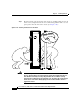
Connecting to the Front Grounding Receptacle
Use the following procedure to connect the supplemental grounding cable to front
grounding receptacle.
Step 1 Loosen the two captive screws on each side of the air filter door and pivot the door
open (
Figure 3-12).
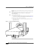
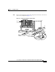
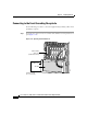
Figure 3-12 Opening the Air Filter Door
ALARM
CS
C
0
FAIL
1
0
1
2
E
NABL
ED
SFC
Q OC-3/STM-POS
6DS3–SMB P
/
H
/
F
12DS3–SMB P
/
H
/
F
RX
TX
11
RX
OC-48/STM-16-SCPOS
OC-12/STM-4 ATM
FAST ETERNET
ROUTE PROCESSOR
26195
Switch fabric
card cage
(behind filter door)
Air filter door
Captive screws
(2 on each side)
Air filter