
User Guide

3-23
Cisco 12016, Cisco 12416, and Cisco 12816 Router Installation and Configuration Guide
OL-11495-01
Chapter 3 Installing the Router
Supplemental Bonding and Grounding Connections
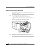
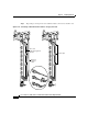
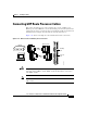
Step 2 Attach the grounding cable to the chassis (Figure 3-13):
a. Insert two M6 bolts through the grounding holes in the chassis.
b. Place the cable lug over the bolts and secure with the locking washers and
nuts.
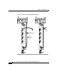
Figure 3-13 Router Front Bonding and Grounding Receptacles
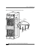
Step 3 Prepare the other end of the grounding wire and connect it to the appropriate
grounding point at your site to ensure an adequate earth ground.
ALARM
C
SC
0
FA
IL
1
0
1
2
EN
ABLE
D
S
FC
Q OC-3/STM-POS
6DS3–SMB P
/
H
/
F
12DS3–SMB P
/
H
/
F
RX
TX
11
RX
OC-48/STM-16-SCPOS
OC-12/STM-4 ATM
FAST ETERNET
ROUTE PROCESSOR
28022
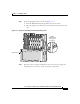
Air filter door
NEBS
supplemental
earth ground
receptacle