
User Guide

3-47
Cisco 12016, Cisco 12416, and Cisco 12816 Router Installation and Configuration Guide
OL-11495-01
Chapter 3 Installing the Router
Installing the Front Covers of Cisco 12016 Original Series Routers
Installing the Front Covers of Cisco 12016 Original
Series Routers
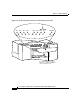
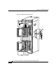
The chassis front covers for the power shelf and upper blower module, upper card
cage, lower card cage, and lower blower module are fastened to the chassis by ball
studs on the front of the chassis (
Figure 3-26).
Note The front cover for power shelf and upper blower module is packaged in the
accessory kit to permit the foam shipping cap to fit securely on the top of the
router and protect the router without damaging the front cover.
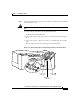
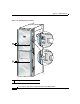
Step 1 Hold the front cover by its outside edges and align the ball studs with the ball stud
clips on the front of the chassis.
Step 2 Push the front cover into the ball stud clips and the front cover is flush with the
front of the chassis.
Step 3 Repeat Step 1 and Step 2 for the remaining front covers.