
User Guide

Chapter 5 Troubleshooting the Installation
Troubleshooting the Power Subsystem
5-14
Cisco 12016, Cisco 12416, and Cisco 12816 Router Installation and Configuration Guide
OL-11495-01
Additional Power Subsystem Troubleshooting Information
This section contains additional troubleshooting information to help you isolate
the cause of a power problem.
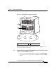
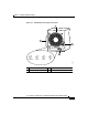
The MBus modules powering the alphanumeric displays on the RP and line cards
are powered by +5
VDC from the backplane. The blower modules use –48 VDC
from the backplane. If both the RP and the blower modules are operating, all
internal correct DC voltages are present.
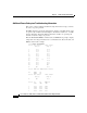
Enter the show environment command at the user EXEC mode prompt to display
temperature and voltage information for each installed card, blower module, and
PEM as shown in this example:
router#show environment
Slot # Hot Sensor Inlet Sensor
(deg C) (deg C)
1 38.0 32.5
3 36.5 39.0
5 37.0 37.0
7 36.0 32.0
16 26.0 26.0
17 27.5 27.5
18 27.0 27.5
19 0.0 0.0
20 27.0 27.5
21 28.0 28.0
22 28.0 28.0
24 47.0 NA
29 NA 22.0
Slot # PEM Over Temperature Sensors
24 PEM1 OK
PEM2 OK
Slot # Hot Sensor Inlet Sensor
(deg C) (deg C)
29 NA 22.0
Slot # 3V 5V MBUS 5V
(mv) (mv) (mv)
1 3296 5016 5048
3 3284 4976 5000
5 3308 5008 5048
7 3296 5016 5000