
User Guide

Chapter 1 Product Overview
Physical and Functional Description of Router
1-2
Cisco 12016, Cisco 12416, and Cisco 12816 Router Installation and Configuration Guide
OL-11495-01
Physical and Functional Description of Router
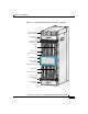
The Cisco 12000 series router chassis is a sheet-metal enclosure that houses router
components. The major components consist of three power supplies, upper and
lower line card cages, a switch fabric card cage, and upper and lower blower
modules. Power is distributed to these components over the chassis backplane.
All router models contain the following major components (Figure 1-1):
• Power shelf and power supplies—Three AC or DC power entry modules
(PEMs) provide power to the router. See the
“AC and DC Power Subsystems”
section on page 1-4 for additional information.
• Upper blower module—Supplies cooling air to the upper half of the router so
it does not overheat. See the
“Blower Module” section on page 1-44 for
additional information.
• Upper and lower cable management brackets—Used to neatly route line card
cables. See the
“Upper and Lower Cable Management Brackets” section on
page 1-43 for additional information.
• Upper Line card and Route Processor card cage—Has 8 user-configurable
slots that support a combination of line cards, a route processor (RP), and an
alarm card. See the
“Alarm Card, Line Card, and Rout Processor Overview”
section on page 1-21 for additional information.
• Switch fabric card cage—Located behind the air filter door, this card cage
contains 5 slots for the switch fabric card set. The switch fabric card set is
made up of 3 switch fabric cards (SFCs) and 2 clock scheduler cards (CSCs).
See the
“Switch Fabric Overview” section on page 1-19 for additional
information.
• Lower Line card and Route Processor card cage—Has 8 user-configurable
slots that support a combination of line cards, a redundant route processor
(RP), and an alarm card. See the
“Alarm Card, Line Card, and Rout Processor
Overview” section on page 1-21 for additional information.
• Lower blower module—Supplies cooling air to the lower half of the router so
it does not overheat. See the
“Blower Module” section on page 1-44 for
additional information.
• Chassis backplane (not shown)—Distributes power to card cages and to the
blower modules.