
User Guide


Chapter 7 Maintaining the Router
Removing and Replacing the DC-Input Power Shelf
7-76
Cisco 12016, Cisco 12416, and Cisco 12816 Router Installation and Configuration Guide
OL-11495-01
Step 11 Power on the source DC circuit breakers for the PEMs.
Step 12 Verify the polarity and voltage readings across the pairs of positive and negative
terminal studs:
• All voltage readings should be –48 to –60 VDC
Caution If any of the voltage readings are not within the specified range, do not proceed.
Check for correct polarity and DC source voltage.
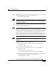
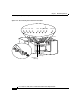
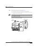
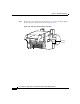
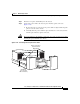
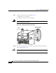
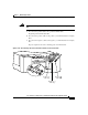
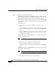
Step 13 Reinstall the power cable cover (Figure 7-47).
Figure 7-47 Reinstalling the Source DC Power Cable Cover
Step 14 Power off the source DC circuit breakers for the PEMs.
Step 15 Install all of the DC PEMs as described in the “Removing and Replacing a DC
PEM” procedure on page 60 beginning with Step 5.
27219
Ground
–
+
Cover standoff
Cover with slotted screw hole;
fastens to standoff in middle
of cable connection area.