C H A P T E R 2 Cards Specifications This chapter contains specific information about cards for dense wavelength division multiplexing (DWDM) applications in the Cisco ONS 15454. Note The terms "Unidirectional Path Switched Ring" and "UPSR" may appear in Cisco literature. These terms do not refer to using Cisco ONS 15xxx products in a unidirectional path switched ring configuration.
Chapter 2 Cards Specifications 2.1 Card Overview • Multiplexer and demultiplexer cards multiplex and demultiplex DWDM optical channels. The cards consist of three main modules: an optical plug-in, a microprocessor, and a DC/DC converter. ONS 15454 multiplexer and demultiplexer cards include the 32-Channel Multiplexer (32MUX-O), the 32-Channel Demultiplexer (32DMX-O), the single-slot 32-Channel Demultiplexer (32DMX), and the 4-Channel Multiplexer/Demultiplexer (4MD-xx.x).
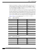
Chapter 2 Cards Specifications 2.1 Card Overview Table 2-2 AD-2C-xx.x Channel Pairs (continued) Band IDs Add/Drop Channel IDs Add/Drop Wavelengths (nm) Band 42.1 (D) 42.1, 42.9 and 43.7, 44.5 1542.14, 1542.94 and 1543.73, 1544.53 Band 46.1 (E) 46.1, 46.9 and 47.7, 48.5 1546.12, 1546.92 and 1547.72, 1548.51 Band 50.1 (F) 50.1, 50.9 and 51.7, 52.5 1550.12, 1550.92 and 1551.72, 1552.52 Band 54.1 (G) 54.1, 54.9 and 55.7, 56.5 1554.13, 1554.94 and 1555.75, 1556.55 Band 58.1 (H) 58.1, 58.
Chapter 2 Cards Specifications 2.1 Card Overview Table 2-4 AD-4B-xx.x Channel Sets Band IDs Add/Drop Channel IDs Add/Drop Wavelengths (nm) Band 54.1 (G) B54.1 1554.13 Band 58.1 (H) B58.1 1558.17 • Transponder (TXP) and muxponder (MXP) cards convert the “gray” optical client interface signals into trunk signals that operate in the “colored” DWDM wavelength range. Transponding or muxponding is the process of converting the signals between the client and trunk wavelengths.
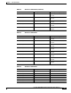
Chapter 2 Cards Specifications 2.1 Card Overview Table 2-5 Cisco ONS 15454 DWDM Cards Card Part Number Description Optical Service Channel Cards OSCM 15454-OSCM= The OSCM card has one set of optical ports and one Ethernet port located on the faceplate. The card operates in Slots 8 and 10. An OSC is a bidirectional channel connecting all the nodes in a ring. The channel transports OSC overhead that is used to manage ONS 15454 DWDM networks.
Chapter 2 Cards Specifications 2.1 Card Overview Table 2-5 Cisco ONS 15454 DWDM Cards (continued) Card Part Number Description OPT-BST-E 15454-OPT-BST-E= The OPT-BST-E card is designed to support up to 64 channels at 50 GHz channel spacing. It is a C-band DWDM EDFA with OSC add-and-drop capability. Its maximum output power is 21 dBm. To control the gain tilt, the OPT-BST-E is equipped with a built-in VOA.
Chapter 2 Cards Specifications 2.1 Card Overview Table 2-5 Cisco ONS 15454 DWDM Cards (continued) Card Part Number Description AD-1C-xx.x 15454-AD-1C-xx.x= The AD-1C-xx.x card passively adds or drops one of the 32 channels utilized within the 100 GHz-spacing of the DWDM card. There are thirty-two versions of this card, each designed only for use with one wavelength. Each wavelength version of the card has a different part number. The AD-1C-xx.
Chapter 2 Cards Specifications 2.1 Card Overview Table 2-5 Cisco ONS 15454 DWDM Cards (continued) Card Part Number Description 32WSS 15454-32WSS= The 32WSS card has seven sets of ports located on the faceplate. The card takes up two slots and operates in Slots 1-2, 3-4, 5-6, 12-13, 14-15, or 16-17. The 32WSS card performs channel add/drop processing within the ONS 15454 DWDM node. The 32WSS card works in conjunction with the 32DMX card to implement ROADM functionality.
Chapter 2 Cards Specifications 2.1 Card Overview Table 2-5 Cisco ONS 15454 DWDM Cards (continued) Card Part Number Description TXP_MR_10E 15454-10E-L1-xx.x= The 10 Gbps Transponder-100 GHz-Tunable xx.xx-xx.xx (TXP_MR_10E) card has two sets of ports located on the faceplate and can be installed in Slots 1 to 6 and Slots 12 to 17. It is a multirate transponder for the ONS 15454 platform.
Chapter 2 Cards Specifications 2.1 Card Overview Table 2-5 Cisco ONS 15454 DWDM Cards (continued) Card Part Number Description TXPP_MR_2.5G 15454-MRP-L1-xx.x= The 2.5 Gbps Multirate Transponder-Protected-100 GHz-Tunable xx.xxxx. xx (TXPP_MR_2.5G) card has three sets of ports located on the faceplate and can be installed in Slots 1 to 6 and Slots 12 to 17. It processes one 8 Mbps to 2.488 Gbps signal (client side) into two 8 Mbps to 2.5 Gbps, 100-GHz DWDM signals (trunk side).
Chapter 2 Cards Specifications 2.1 Card Overview Table 2-5 Cisco ONS 15454 DWDM Cards (continued) Card Part Number Description MXP_2.5G_10E 15454-10ME-xx.x= The 2.5 Gbps-10 Gbps Muxponder-100 GHz-Tunable xx.xx-xx.xx (MXP_2.5G_10E) card has nine sets of ports located on the faceplate and can be installed in Slots 1 through 6 and 12 through 17. It is a DWDM muxponder for the ONS 15454 platform that supports full optical transparency on the client side. The card multiplexes four 2.
Chapter 2 Cards Specifications 2.2 Card Specifications Table 2-5 Cisco ONS 15454 DWDM Cards (continued) Card Part Number MXP_MR_10DME_C 15454-10DME-C= MXP_MR_10DME_L 15454-10DME-L= Description The MXP_MR_10DME_C and MXP_MR_10DME_L cards aggregate a mix of client SAN service client inputs (GE, FICON, and Fibre Channel) into one 10-Gbps STM-64/OC-192 DWDM signal on the trunk side. It provides one long-reach STM-64/OC-192 port per card and is compliant with Telcordia GR-253-CORE and ITU-T G.957.
Chapter 2 Cards Specifications 2.2.
Chapter 2 Cards Specifications 2.2.1 Common Control Cards The TCC2 performs all system-timing functions for each ONS 15454. The TCC2 monitors the recovered clocks from each traffic card and two building integrated timing supply (BITS) ports for frequency accuracy. The TCC2 selects a recovered clock, a BITS, or an internal Stratum 3 reference as the system-timing reference. You can provision any of the clock inputs as primary or secondary timing sources.
Chapter 2 Cards Specifications 2.2.
Chapter 2 Cards Specifications 2.2.1 Common Control Cards The node database, IP address, and system software are stored in TCC2P card nonvolatile memory, which allows quick recovery in the event of a power or card failure. The TCC2P card performs all system-timing functions for each ONS 15454. The TCC2P card monitors the recovered clocks from each traffic card and two BITS ports for frequency accuracy.
Chapter 2 Cards Specifications 2.2.
Chapter 2 Cards Specifications 2.2.2 Optical Service Channel Cards • PROT: Connected to the other MS-ISC-100T ports The TCC is connected to the MS LAN by its front panel port. The back panel Ethernet port is disabled and cannot be used in the MS node. 2.2.2 Optical Service Channel Cards The Optical Service Channel (OSC) is a bidirectional channel that connects all the nodes in a DWDM ring that transports general-purpose information without affecting client traffic.
Chapter 2 Cards Specifications 2.2.3 Optical Add and Drop Cards Table 2-7 OSC-CSM Card Optical Specifications (continued) Parameter Condition Min Max Unit Insertion loss LINERX – OSCTX 0.5 1.4 dB LINERX – COMTX 0.4 1.2 dB OSCRX – LINETX 1.2 2.2 dB COMRX – LINETX 1.2 2.
Chapter 2 Cards Specifications 2.2.3 Optical Add and Drop Cards Table 2-8 32WSS Card Parameters and Performance Parameter Condition Min Typical Max Unit –0.5 dB bandwidth EXP RX => COM TX +/–115 –0.5 dB bandwidth Add 1, 32 => COM TX +/–135 Insertion loss EXP RX => COM TX — — 11.3 COM RX => EXP TX — — 1.5 Add 1, 32 => COM TX — — 7.6 COM RX => DROP TX 6 — 8.
Chapter 2 Cards Specifications 2.2.3 Optical Add and Drop Cards Table 2-8 32WSS Card Parameters and Performance (continued) Parameter Condition Min Directivity Add 1,32 <=> Add 1,32 40 Typical Max Unit — — dB Add 1, 32 <=> EXP RX Return loss — 40 — — dB Maximum optical input power — 300 — — mW Maximum AWG startup time — — — 10 min. 2.2.3.
Chapter 2 Cards Specifications 2.2.3 Optical Add and Drop Cards Table 2-9 32WSS-L Card Parameters and Performance (continued) Parameter Condition Min Typical Max Unit In-band chromatic dispersion All paths –20 — +20 ps/nm Group delay ripple All paths –10 — +10 ps In-band PMD All paths — — 1 ps Optical power/VOA attenuation setting resolution — — — 0.1 dB Optical power setting accuracy — –0.7 0.1 + 0.7 dB Optical power setting precision — –0.4 0.1 + 0.
Chapter 2 Cards Specifications 2.2.3 Optical Add and Drop Cards Table 2-10 32DMX Card Optical Parameters and Insertion Loss Parameter Condition Min Typical Max Unit –1 dB Bandwidth +/–110 — — pm –3 dB Bandwidth COM RX => TX 1, 32 (OUT) +/–200 — — Insertion Loss COM RX => TX 1, 32 — — 5.5 dB Adjacent Crosstalk COM RX => TX 1, 32 26 — — dB Nonadjacent Crosstalk 34 — — Total Crosstalk 20 — — PDL COM RX => TX 1, 32 — — 0.
Chapter 2 Cards Specifications 2.2.3 Optical Add and Drop Cards When output ports are connected to the client equipment, an external bulk attenuator might be required to match the receive (Rx) window of the interface. Table 2-11 defines the internal optical parameters. Table 2-11 32DMX-L Card Optical Parameters Parameter Condition Min Typical Max Unit –1 dB bandwidth +/–100 — — pm –3 dB bandwidth COM RX => TX 1, 32 (OUT) +/–200 — — Insertion loss COM RX => TX 1, 32 — — 5.
Chapter 2 Cards Specifications 2.2.3 Optical Add and Drop Cards Table 2-12 32MUX-O Card Optical Parameters Parameter Min Typical Max Unit –1 dB bandwidth 160 — 300 pm In-band ripple — — 0.5 dB Insertion loss 4 — 8.5 dB Insertion loss disuniformity — — 1.5 dB Adjacent crosstalk 23 — — dB Nonadjacent crosstalk 30 — — dB Total crosstalk 20 — — dB PDL — — 1.5 dB In-band chromatic dispersion –20 — +20 ps/nm In-band PMD — — 0.
Chapter 2 Cards Specifications 2.2.3 Optical Add and Drop Cards Table 2-13 32DMX-O Card Optical Parameters Parameter Min Typical Max Unit –1 dB bandwidth 160 — 300 pm In-band ripple — — 0.5 dB Insertion loss 4 — 8.5 dB Insertion loss disuniformity — — 1.5 dB Adjacent crosstalk 23 — — dB Nonadjacent crosstalk 30 — — dB Total crosstalk 20 — — dB PDL — — 1.5 dB In-band chromatic dispersion –20 — +20 ps/nm In-band PMD — — 0.
Chapter 2 Cards Specifications 2.2.3 Optical Add and Drop Cards Table 2-14 4MD-xx.x Card Optical Parameters Optical Parameters Value Maximum insertion loss demultiplex section 3.2 dB Maximum insertion loss multiplex section 3.6 dB at VOA min attenuation Adjacent crosstalk 25 dB Nonadjacent crosstalk 38 dB VOA dynamic range 30 dB 2.2.3.8 C-Band OADM Filter Cards Table 2-15 to Table 2-19 define optical parameters for the AD-1B-xx.x, AD-4B-xx.x, AD-1C-xx.x, AD-2C-xx.x, and AD-4C-xx.x cards.
Chapter 2 Cards Specifications 2.2.3 Optical Add and Drop Cards Table 2-16 AD-4B-xx.x Card Optical Parameters (continued) Optical Parameters Value In-band ripple 0.5 dB at VOA minimum attenuation Out-of-band ripple (COM RX – Exp TX) 0.3 dB Left/Right adjacent crosstalk 25 dB First channel nonadjacent crosstalk 30 dB Nonadjacent crosstalk 35 dB Left/Right isolation drop path –26 dB Left/Right isolation add path –13 dB Table 2-17 AD-C-xx.
Chapter 2 Cards Specifications 2.2.3 Optical Add and Drop Cards Table 2-19 AD-4C-xx.x Card Optical Parameters Optical Parameters Value Maximum insertion loss drop section 5.4 dB Maximum insertion loss add section 4.9 dB at VOA min attenuation Maximum insertion loss express section (Exp RX – COM TX) 1.2 dB Maximum insertion loss express section (COM RX – Exp TX) 2.
Chapter 2 Cards Specifications 2.2.4 Optical Amplifiers Table 2-20 MMU Card Optical Specifications (continued) Parameter Condition Notes Min Typical Max Unit Optical power reading resolution All PDs (both real and virtual) — — — 0.1 dB — – 0.1 — 0.
Chapter 2 Cards Specifications 2.2.4 Optical Amplifiers 2.2.4.1 OPT-PRE Card Table 2-21 provides the internal parameters and performance information for the OPT-PRE preamplifier card.
Chapter 2 Cards Specifications 2.2.4 Optical Amplifiers Table 2-22 indicates the extended power and gain range for OPT-PRE card. Table 2-22 OPT-PRE Extended Power and Gain Range Parameter Comment Min Total input signal power range Full channel load See Figure 2-5 for detailed Pin-Pout power mask Maximum output signal power Extended gain range 1 Typical Max Unit –21.5 –4 dBm Single channel See Figure 2-5 for detailed Pin-Pout power mask –39.5 –22 dBm Full channel load 17.0 — 17.
Chapter 2 Cards Specifications 2.2.4 Optical Amplifiers Table 2-23 OPT-BST Card Power and Gain Specification Parameter Comment Min Typical Max Unit Total input signal power range Full channel load; see Figure 2-6 for detailed Pin-Pout power mask –3 — 12 dBm Single channel; see Figure 2-6 for detailed Pin-Pout power mask –21 — –6 dBm Full channel load 17.0 — 17.5 dBm Single channel –1.0 — –0.
Chapter 2 Cards Specifications 2.2.4 Optical Amplifiers Table 2-24 OPT-BST-E Card Power and Gain Specifications (continued) Parameter Comment Min Typical Max Unit Maximum optical amplifier signal gain With tilt controlled at 0 dB — — 23 dB Gain range — 8 — 23 dB Extended gain range Gain range with tilt uncontrolled 23 — 26 dB Gain tilt error at target gain tilt = 0 dB — — — +/– 0.
Chapter 2 Cards Specifications 2.2.
Chapter 2 Cards Specifications 2.2.4 Optical Amplifiers Figure 2-9 shows the internal functional structure for the OPT-BST-L card. Figure 2-9 OPT-BST-L Card Functional Block Diagram MON TX OSC RX P3 COM RX P1 P2 LINE TX APR signal COM TX LINE RX P4 in RX OSC TX P Physical photodiode 134976 MON RX P5 OSC Optical loss (in dB) caused by the OPT-BST-L monitor ports is printed on the card faceplate.
Chapter 2 Cards Specifications 2.2.4 Optical Amplifiers The OPT-AMP-L card implements the following optical safety functions: • OSRI • ALS The OSRI function provides hardware and software capability for shutting down optical power or reducing it to a safe level, whereas the ALS function provides an APR safety mechanism for fiber cuts. Table 2-26 defines the standard and extended gain ranges for the OPT-AMP-L card.
Chapter 2 Cards Specifications 2.2.4 Optical Amplifiers Figure 2-10 OPT-AMP-L Card Standard and Extended Gain Range Figure 2-11 shows the internal functional structure of the OPT-AMP-L card. Cisco ONS 15454 DWDM Engineering and Planning Guide, Release 7.
Chapter 2 Cards Specifications 2.2.5 Dispersion Compensation Units Figure 2-11 OPT-AMP-L Card Functional Block Diagram DC TX DC RX External Mid-Stage Loss OSC RX P7 P2 P3 COM RX P1 P4 OSC Add LINE TX MON TX Transmit Section Receive Section OSC Drop MON RX P5 P6 LINE RX 145256 COM TX OSC TX P Physical photodiode Variable optical attenuator The card faceplate shows the optical loss (in dB) of the monitor ports provided by the OPT-AMP-L card.
Chapter 2 Cards Specifications 2.2.
Chapter 2 Cards Specifications 2.2.5 Dispersion Compensation Units 2.2.5.1 DCU Mechanical Specifications The DCU subrack is designed to comply with all international standards. The DCU shelf is housed in a 1-RU 19" (482.6mm)/23” (584.2mm) rack-mounted shelf [17" (431.8mm) wide, 11" (279.4mm) deep, 1.75" (44.45mm) high] with all front access (fibers, management interfaces when applicable). The depth of the subrack, including cable management, does not exceed the 280 mm requirement.
Chapter 2 Cards Specifications 2.2.6 Transponder, Muxponder, and Optical Cards Table 2-28 Optical Specifications for ONS 15454 DCUs (continued) Units Specifications C Band L Band Insertion Loss [dB] PMD [ps/nm] PDL [dB] ORL [dB] Notes — 15216-DCU-L-300= <3 0.5 <0.1 <45 — 15216-DCU-L-600= <4.2 0.6 Wavelength range 1576 to 1605 nm — 15216-DCU-L-700= <4.6 0.6 — 15216-DCU-L-800= <5 0.7 — 15216-DCU-L-1000= <5.8 0.8 — 15216-DCU-L-1100= <6 0.8 — 15216-DCU-DS-L100= <3.
Chapter 2 Cards Specifications 2.2.6 Transponder, Muxponder, and Optical Cards Table 2-29 Supported C-Band Wavelengths for TXP/MXP Cards (continued) DWDM 10-Gbps TXP/MXP DWDM 2.5-Gbps TXP/MXP DWDM 10-Gbps TXP/MXP (Full C-Band Tunable) Frequency (THz) Wavelength (nm) (2 Ch Tunable) (4 Ch Tunable) (4 Ch Tunable) 195.5 1533.47 — — — 194.9 1538.19 15454-10M-L1-38 15454-10E-L1-38. 15454-DM-L1-38. .1= 1= 1= 194.8 1538.98 15454-10T-L1-38. 1= 194.7 1539.77 15454-10M-L1-39 .
Chapter 2 Cards Specifications 2.2.6 Transponder, Muxponder, and Optical Cards Table 2-29 Supported C-Band Wavelengths for TXP/MXP Cards (continued) DWDM 10-Gbps TXP/MXP DWDM 2.5-Gbps TXP/MXP DWDM 10-Gbps TXP/MXP (4 Ch Tunable) (Full C-Band Tunable) Frequency (THz) Wavelength (nm) (2 Ch Tunable) (4 Ch Tunable) 193.4 1550.12 15454-10M-L1-50 15454-10E-L1-50. 15454-DM-L1-50. .1= 1= 1= 193.3 1550.92 15454-10T-L1-50. 1= 193.2 1551.72 15454-10M-L1-50 .1= 15454-MR-L1-50. 1= 193.1 1552.
Chapter 2 Cards Specifications 2.2.6 Transponder, Muxponder, and Optical Cards Table 2-30 Supported L-Band Wavelengths for Transponder/Muxponder Cards Frequency (THz) Wavelength (nm) DWDM 10-Gbps TXP/MXP (4 Ch Tunable) DWDM 10-Gbps TXP/MXP (Full L-Band Tunable) 190.9 1570.42 — 15454-10E-L1-L= 190.8 1571.24 — 15454-10ME-L= 190.7 1572.06 — 15454-10DME -L= 190.6 1572.89 — 190.5 1573.71 — 190.4 1574.54 — 190.3 1575.37 — 190.2 1576.2 — 190.1 1577.03 — 190 1577.
Chapter 2 Cards Specifications 2.2.6 Transponder, Muxponder, and Optical Cards Table 2-30 Supported L-Band Wavelengths for Transponder/Muxponder Cards (continued) Frequency (THz) Wavelength (nm) DWDM 10-Gbps TXP/MXP (4 Ch Tunable) 188.8 1587.88 15454-10E-L1-87.4= 188.7 1588.73 15454-10ME-87.4= 188.6 1589.57 188.5 1590.41 188.4 1591.26 15454-10E-L1-90.8= 188.3 1592.10 15454-10ME-90.8= 188.2 1592.95 188.1 1593.79 188 1594.64 — 187.9 1595.49 — 187.8 1596.34 — 187.7 1597.
Chapter 2 Cards Specifications 2.2.6 Transponder, Muxponder, and Optical Cards Table 2-31 OC48 ITU-T Channels Available for the ONS 15454 (continued) C-Band Spectrum 15454 OC48 ELR 100 GHz ITU-T Cards Channel (nm) Frequency (THz) X 1532.68 195.6 X 1533.47 195.5 X 1534.28 195.4 X 1535.04 195.3 X 1535.82 195.2 X 1536.61 195.1 X 1538.19 194.9 X 1538.98 194.8 X 1539.77 194.7 X 1540.56 194.6 X 1541.35 194.5 X 1542.14 194.4 X 1542.94 194.3 X 1543.73 194.2 X 1544.
Chapter 2 Cards Specifications 2.2.6 Transponder, Muxponder, and Optical Cards The ONS 15454 OC48 ITU-T cards provide you with 37 separate ITU-T channels to choose from. These wavelengths conform to ITU-T 100-GHz and 200-GHz channel spacing, enabling compatibility with most DWDM systems. Integrating the ONS 15454 OC48 ITU-T cards with third-party DWDM products enables you to design a low-cost, scalable DWDM system with full add/drop capabilities. 2.2.6.
Chapter 2 Cards Specifications 2.2.6 Transponder, Muxponder, and Optical Cards Table 2-32 OC192 ITU-T Channels Available for the ONS 15454 (continued) C-Band Spectrum 15454 OC192 LR 100 GHz ITU-T Cards 1 Channel (nm) Frequency (THz) X 1556.55 192.6 X 1558.17 192.4 X 1558.98 192.3 X 1559.79 192.2 X 1560.61 192.1 1. These wavelengths are shorter lead-time cards and are recommended for deployment. The ONS 15454 offers eight OC192 ITU-T cards.
Chapter 2 Cards Specifications 2.2.6 Transponder, Muxponder, and Optical Cards Table 2-33 Client Services Program Name Client Service Type Client Interface (SFP/XFP) SFP/XFP Product ID (ANSI) SFP/XFP Product ID (ETSI) — Gigabit Ethernet 1000Base-LX (IEEE 802.3) 15454-SFP-GE+-LX 15454E-SFP-GE+-LX 1000Base-SX (IEEE 802.
Chapter 2 Cards Specifications 2.2.
Chapter 2 Cards Specifications 2.2.7 Y-Cable Module Figure 2-13 Multimode Y-Cable Splitter Module Client TX 1x2 Client RX 1x2 TXP W TX TXP W RX TXP P RX 151942 TXP P TX Table 2-34 shows operating parameters for a multimode Y-cable module.
Chapter 2 Cards Specifications 2.2.8 Mechanical Equipment 2.2.8 Mechanical Equipment The following section describes mechanical equipment such as the bay frame, optical shelf, dispersion compensation shelf, Y-cable shelf, fiber storage units, and 32-channel patch-panel units. 2.2.8.
Chapter 2 Cards Specifications 2.2.8 Mechanical Equipment Figure 2-14 Y-Cable Shelf Fiber Routing 144678 Y cable modules LC-LC cables 2.2.8.5 Fiber Storage The fiber storage tray has height of 1 RU and can be installed in 19” (482.6 mm) ANSI or ETSI racks.The fiber storage tray manages all incoming and outgoing fibers for a single ONS 15454 shelf. The minimum fiber bend radius is 1.5” (38.1 mm) or 20 times the cable diameter at any point, whichever is greater.
Chapter 2 Cards Specifications 2.2.8 Mechanical Equipment 32-Channel Patch Panel Shelf Fiber Routing 151601 Figure 2-15 The PP-64 contains 64 LC-LC adapters and manages up to eight multifiber cables. The minimum fiber bend radius is 1.5” (38.1 mm) or 20 times the cable diameter at any point, whichever is greater. The PP-64 is used for both C-band and L-band systems. A label on the front panel enables identification of channel wavelength IDs during installation.
Chapter 2 Cards Specifications 2.2.8 Mechanical Equipment Cisco ONS 15454 DWDM Engineering and Planning Guide, Release 7.