C H A P T E R 17 DLPs E100 to E199 Note The terms "Unidirectional Path Switched Ring" and "UPSR" may appear in Cisco literature. These terms do not refer to using Cisco ONS 15xxx products in a unidirectional path switched ring configuration. Rather, these terms, as well as "Path Protected Mesh Network" and "PPMN," refer generally to Cisco's path protection feature, which may be used in any topological network configuration.
Chapter 17 DLPs E100 to E199 DLP- E101 Apply a Lock On in a 1+1 Group If the Force switch is successful, CTC shows both ports as [FORCE TO PROTECT] (or [FORCE TO WORKING]). This indication is shown whether or not the ONS 15600 system has been able to move traffic from one port to the other. If the Bidirectional switching check box is checked, both the near-end and far-end nodes switch to the designated protection ports.
Chapter 17 DLPs E100 to E199 DLP- E102 Apply a Lockout in a 1+1 Group Step 6 Click Yes in the confirmation dialog box. The lock on has been applied and traffic cannot be switched from that port. See the “DLP-E168 Clear a Lock On or Lockout in a 1+1 Protection Group” task on page 17-53 as needed. Step 7 Return to your originating procedure (NTP).
Chapter 17 DLPs E100 to E199 DLP- E104 Initiate a Force Switch to a Path Protection Circuit Step 2 Click the path you want to switch and then click Edit. Step 3 In the Edit Circuit window, click the Path Protection Selectors tab. Step 4 In the Switch State column, click the row for the path you want to switch and select Manual to Protect or Manual to Working as appropriate. Step 5 Click Apply.
Chapter 17 DLPs E100 to E199 DLP- E105 Create a DCC Tunnel DLP-E105 Create a DCC Tunnel Purpose This task creates a data communications channel (DCC) tunnel to transport traffic from third-party SONET equipment across ONS 15600 networks. Tunnels can be created on the Section DCC (SDCC) channel (D1-D3) (if not used by a node as a terminated DCC), or any Line DCC (LDCC) channel (D4-D6, D7-D9, or D10-D12).
Chapter 17 DLPs E100 to E199 DLP- E106 Clean Fiber Connectors Step 5 In the Destination area, complete the following: • Node—Choose the destination node. • Slot—Choose the destination slot. • Port—Choose the destination port. • Channel—Shown if you chose DCC Tunnel-D1-D3 as the tunnel type.
Chapter 17 DLPs E100 to E199 DLP- E107 Clean the Fiber Adapters Step 3 b. Place the connector tip at the top of the slot at a slight angle. In a single stroke, move the connector down the wipe without lifting the connector from the wipe. Before lifting the connector from the wipe, straighten the connector. c. Repeat the single stroke motion on each side of the alignment pins to clean the entire connector face. d. Blow off any wipe lint left on the fiber connector using the compressed air.
Chapter 17 DLPs E100 to E199 DLP- E108 Verify that a 1+1 Working Port is Active d. Step 3 Remove and insert the scrub tool tip several times to clean the fiber adapter. To remove loose particles from the fiber adapter: a. Remove the dust cap from the rinse tool. Note If the absorbent pad on the rinse tool needs replacement, slide the old pad and mesh retainer off of the rinse tool tube. Slide the new absorbent pad and mesh retainer over the rinse tip onto the rinse tool tube.
Chapter 17 DLPs E100 to E199 DLP- E109 Drill Holes to Anchor and Provide Access to the Bay Assembly c. Step 4 Verify that the working slot is carrying traffic (Working/Active). Note Step 5 Click Yes in the confirmation dialog box. If the slot is not active, look for conditions or alarms that might be preventing the card from carrying working traffic. Refer to the Cisco ONS 15600 Troubleshooting Guide for procedures to clear alarms.
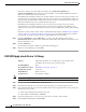
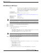
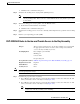
Chapter 17 DLPs E100 to E199 DLP- E109 Drill Holes to Anchor and Provide Access to the Bay Assembly Figure 17-1 Floor Template A A UNDERFLOOR CMP CABLE C B OPTICAL CABLE ACCESS G F H UNDERFLOOR CMP CABLE D B G H C F D OPTICAL CABLE ACCESS E UNDERFLOOR SYSTEM CABLE H E H UNDERFLOOR SYSTEM CABLE Bolt Hole Pattern UNDERFLOOR POWER UNDERFLOOR POWER UNDERFLOOR NETWORK CABLE UNDERFLOOR NETWORK CABLE OPTICAL CABLE ACCESS C CABLE ROUTING MODULE B J J F A H H D FRONT D F A CAB
Chapter 17 DLPs E100 to E199 DLP- E110 Assign a Name to a Port DLP-E110 Assign a Name to a Port Purpose This task assigns a name to a port on any ONS 15600 card. Tools/Equipment None Prerequisite Procedures DLP-E26 Log into CTC, page 16-33 NTP-E21 Verify Card Installation, page 4-2 Required/As Needed As needed Onsite/Remote Onsite or remote Security Level Provisioning or higher Step 1 Double-click the card that has the port you want to provision. Step 2 Click the Provisioning tab.
Chapter 17 DLPs E100 to E199 DLP- E112 Provision a Half Circuit Source and Destination on a BLSR or 1+1 Step 2 • Reversion time—If Revertive is checked, click the Reversion time field and choose a reversion time from the drop-down list. The range is 0.5 to 12.0 minutes. The default is 5.0 minutes. This is the amount of time that will elapse before the traffic reverts to the working path. Traffic can revert when conditions causing the switch are cleared.
Chapter 17 DLPs E100 to E199 DLP- E113 Provision a Half Circuit Source and Destination on a Path Protection DLP-E113 Provision a Half Circuit Source and Destination on a Path Protection Purpose This task provisions a half circuit source and destination for a path protection. This task is used to create path protection selectors on the node.
Chapter 17 DLPs E100 to E199 DLP- E114 Provision Section DCC Terminations DLP-E114 Provision Section DCC Terminations Purpose This task creates SONET Section DCC terminations required for alarms, administration data, signal control information, and messages.
Chapter 17 DLPs E100 to E199 DLP- E114 Provision Section DCC Terminations Step 8 If you checked OSI, complete the following steps. If you checked IP only, continue with Step 9. a. Click Next. b. Provision the following fields: – Router—Choose the OSI router. – ESH—Sets the End System Hello (ESH) propagation frequency. End system NEs transmit ESHs to inform other ESs and ISs about the NSAPs it serves. The default is 10 seconds. The range is 10 to 1000 seconds.
Chapter 17 DLPs E100 to E199 DLP- E115 Change the Service State for a Port DLP-E115 Change the Service State for a Port Purpose This task puts a port in service or removes a port from service. Tools/Equipment None Prerequisite Procedures DLP-E26 Log into CTC, page 16-33 Required/As Needed As needed Onsite/Remote Onsite or remote Security Level Provisioning or higher Step 1 In node view, double-click the card with the port(s) you want to put in or out of service. The card view appears.
Chapter 17 DLPs E100 to E199 DLP- E116 Remap the K3 Byte Step 8 Return to your originating procedure (NTP). DLP-E116 Remap the K3 Byte Purpose This task provisions the K3 byte. Do not remap the K3 byte unless specifically required to run an ONS 15600 BLSR through third-party equipment. This task is unnecessary for most users.
Chapter 17 DLPs E100 to E199 DLP- E120 Remove the Narrow CRMs Step 3 Step 4 From the Auto-refresh drop-down list choose one of the following options: • None: This option disables the auto-refresh feature. • 15 Seconds: This option sets the window auto-refresh to 15-second time intervals. • 30 Seconds: This option sets the window auto-refresh to 30-second time intervals. • 1 Minute: This option sets the window auto-refresh to one-minute time intervals.
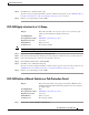
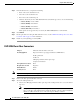
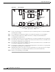
Chapter 17 DLPs E100 to E199 DLP- E120 Remove the Narrow CRMs Figure 17-2 Narrow CRMs Right narrow CRM Left cable radius Right cable radius 96608 Left narrow CRM Step 2 Lift the cable router slightly and pull it away from the bay. Step 3 Repeat this procedure for the router on the other side. Step 4 Unscrew and remove the cable radius pieces at the lower right and left sides of the shelf. Step 5 Return to your originating procedure (NTP). Cisco ONS 15600 Procedure Guide, R8.
Chapter 17 DLPs E100 to E199 DLP- E121 Replace the Existing 600-mm Kick Plates with 900-mm Kick Plates DLP-E121 Replace the Existing 600-mm Kick Plates with 900-mm Kick Plates Purpose This task removes the existing 600-mm (23.6-inch) kick plates so you can install the 900-mm (35.4-inch) kick plates. You should install 900-mm (35.4-inch) kick plates if you plan to install the wide CRMs.
Chapter 17 DLPs E100 to E199 DLP- E123 Clear a Manual Switch on a Node Timing Reference This operation commands the node to switch to the reference you have selected if the SSM quality of the reference is not lower than the current timing reference. Step 4 Click the Apply button. Step 5 Click Yes in the confirmation dialog box. If the selected timing reference is an acceptable valid reference, the node switches to the selected timing reference.
Chapter 17 DLPs E100 to E199 DLP- E124 Set the Optical Power Received Nominal Value DLP-E124 Set the Optical Power Received Nominal Value Purpose This task sets the optical power received (OPR) threshold for each optical card. The ONS 15600 node uses the value set as a performance monitoring parameter to determine if the power level has degraded.
Chapter 17 DLPs E100 to E199 DLP- E126 Provision the IIOP Listener Port on the CTC Computer • Other Constant—If Port 683 is not used, type the IIOP port specified by your firewall administrator. Step 3 Click Apply. Step 4 When the Change Network Configuration message appears, click Yes. Both Timing and Shelf controllers (TSCs) reboot, one at a time. The reboot will take approximately 15 minutes. Step 5 Return to your originating procedure (NTP).
Chapter 17 DLPs E100 to E199 DLP- E127 Edit Path Protection Circuit Path Selectors DLP-E127 Edit Path Protection Circuit Path Selectors Purpose This task changes the path protection SF and SD thresholds, the reversion time, and payload defect indication–path (PDI-P) settings.
Chapter 17 DLPs E100 to E199 DLP- E128 Change the Node Name, Date, Time, and Contact Information DLP-E128 Change the Node Name, Date, Time, and Contact Information Purpose This task changes basic node information such as node name, date, time, and contact information.
Chapter 17 DLPs E100 to E199 DLP- E129 Enable Dialog Box Do-Not-Display Option DLP-E129 Enable Dialog Box Do-Not-Display Option Purpose This task enables or disables the “Do not show this dialog again” dialog box preference for subsequent sessions or disables the do not display option.
Chapter 17 DLPs E100 to E199 DLP- E131 Change Security Policy on Multiple Nodes Step 3 Step 4 In the User Lockout area, you can modify the following: • Failed Logins Before Lockout—Choose the number of failed login attempts a user can make before the user is locked out from the node. You can choose a value between 0 and 10. • Manual Unlock by Superuser—Check this box if you want to allow a user with Superuser privileges to manually unlock a user who has been locked out from a node.
Chapter 17 DLPs E100 to E199 DLP- E132 Change User Password and Security Levels for a Single Node Step 6 • Manual Unlock by Superuser—Check this box if you want to allow a user with Superuser privileges to manually unlock a user who has been locked out from a node. The user will remain locked out until a Superuser manually unlocks the user. • Lockout Duration—Choose the amount of time the user will be locked out after a failed login.
Chapter 17 DLPs E100 to E199 DLP- E133 Change User and Security Settings for Multiple Nodes Note Step 5 User settings that you changed during this task will not appear until that user logs off and logs back in again. Return to your originating procedure (NTP). DLP-E133 Change User and Security Settings for Multiple Nodes Purpose This task changes an existing user’s settings for multiple nodes.
Chapter 17 DLPs E100 to E199 DLP- E135 Log Out a User on a Single Node DLP-E135 Log Out a User on a Single Node Purpose This task logs out a user from a single node. Tools/Equipment None Prerequisite Procedures DLP-E26 Log into CTC, page 16-33 Required/As Needed As needed Onsite/Remote Onsite or remote Security Level Superuser Step 1 In node view, click the Provisioning > Security > Active Logins tabs. Step 2 Choose the user you want to log out. Step 3 Click Logout.
Chapter 17 DLPs E100 to E199 DLP- E137 Check the Network for Alarms and Conditions Step 7 Click OK. A confirmation dialog box appears. Step 8 Click OK. Step 9 Return to your originating procedure (NTP). DLP-E137 Check the Network for Alarms and Conditions Purpose This task verifies that no alarms or conditions exist on the network.
Chapter 17 DLPs E100 to E199 DLP- E141 Disable Proxy Service Using Netscape (Windows and UNIX) Note If your computer is running Windows XP, you can select Control Panel directly from the Start menu. Make sure that you are in Classic View before continuing with this procedure. Step 2 In the Control Panel window, choose Internet Options. Step 3 From the Internet Properties dialog box, click Connections > LAN Settings.
Chapter 17 DLPs E100 to E199 DLP- E142 Install the Narrow CRMs DLP-E142 Install the Narrow CRMs Purpose This task installs narrow CRMs on the ONS 15600 bay.
Chapter 17 DLPs E100 to E199 DLP- E143 Install the Wide CRMs DLP-E143 Install the Wide CRMs Purpose This task installs the wide CRMs.
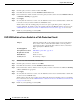
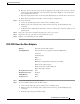
Chapter 17 DLPs E100 to E199 DLP- E143 Install the Wide CRMs Figure 17-3 CRM Screw Holes (Front) 96609 CRM screw holes (front) Step 7 Align the front of the CRM keyholes with the screws and carefully slide the CRM down so it rests on the screws. Tighten the screws, starting with the bottom screw and proceeding up to the middle and top screws. Step 8 Locate the two screw holes on the side of the shelf toward the rear of the bay and make sure they are aligned with the holes on the CRM.
Chapter 17 DLPs E100 to E199 DLP- E144 Use the Reinitialization Tool to Clear the Database and Upload Software (Windows) Step 9 Repeat Steps 5 through 8 for the left-side CRM. Step 10 Return to your originating procedure (NTP). DLP-E144 Use the Reinitialization Tool to Clear the Database and Upload Software (Windows) Purpose This task reinitializes the ONS 15600 using the CTC reinitialization (reinit) tool on a Windows computer.
Chapter 17 DLPs E100 to E199 DLP- E145 Connect the PDU Ground Cables to the PDU Step 6 Caution Step 7 • Activate/Revert—Check this box to activate the uploaded software (if the software is a later than the installed version) or revert to the uploaded software (if the software is earlier than the installed version) as soon as the software file is uploaded.
Chapter 17 DLPs E100 to E199 DLP- E145 Connect the PDU Ground Cables to the PDU Note A shunt is preinstalled between logic and frame ground to bond the two grounds. If you are providing a separate logic ground, remove this shunt on both sides before installing the PDU frame ground.
Chapter 17 DLPs E100 to E199 DLP- E146 Install Isolated Logic Ground DLP-E146 Install Isolated Logic Ground Purpose This optional task isolates logic ground from frame ground if required by site specifications. The ONS 15600 ships with the frame ground strapped to the logic ground with metal shunts at the PDU input terminals. Tools/Equipment Screwdriver Ground wire Two-hole power lugs, 0.625-inch hole spacing, 0.
Chapter 17 DLPs E100 to E199 DLP- E147 Check BLSR or Path Protection Alarms and Conditions DLP-E147 Check BLSR or Path Protection Alarms and Conditions Purpose This task checks a BLSR or a path protection for alarms and conditions before performing any major administrative change to the ring such as adding and removing nodes.
Chapter 17 DLPs E100 to E199 DLP- E152 Install Public-Key Security Certificate Step 5 b. In the Set West Protection Operation dialog box, choose CLEAR from the drop-down list. Click OK. c. In the Confirm BLSR Operation dialog box, click Yes. To clear a Force switch on the east line: a. Right-click the BLSR east port where you want to clear the protection switch and choose Set East Protection Operation. Ports with a Force switch applied are marked with an F. b.
Chapter 17 DLPs E100 to E199 DLP- E153 Changing the Maximum Number of Session Entries for Alarm History Step 3 • Yes—Removes the modified Java policy file from your PC. Choose this option only if you will log into ONS 15600s running Software R1.1 or later. • No—Does not remove the modified Java policy file from your PC. Choose this option if you will log into ONS 15600s running Software R1.0. If you choose No, this dialog box will appear every time you log into the ONS 15600.
Chapter 17 DLPs E100 to E199 DLP- E154 Delete Alarm Severity Profiles Step 3 Step 4 Click Apply and OK. Note Setting the Maximum History Entries value to the high end of the range uses more CTC memory and could impair CTC performance. Note This task changes the maximum history entries recorded for CTC sessions. It does not affect the maximum number of history entries viewable for a network, node, or card. Return to your originating procedure (NTP).
Chapter 17 DLPs E100 to E199 DLP- E155 Enable Alarm Filtering Step 9 Step 10 To remove the alarm profile from the Provisioning > Alarm Profiles > Alarm Profile Editor window, right-click the column of the profile you deleted and choose Remove from the shortcut menu. Note If a node and profile combination is selected but does not exist, a warning appears: “One or more of the profile(s) selected do not exist on one or more of the node(s) selected.
Chapter 17 DLPs E100 to E199 DLP- E155 Enable Alarm Filtering Figure 17-7 Step 3 Conditions Window Filter Dialog Box In the Show Severity area, alarm severities appear. All of the applicable severities are checked by default. If a severity is checked, it appears in the alarm list. Note The Alarms window and History window have Critical (CR), Major (MJ), Minor (MN), and Not Alarmed (NA) severities available. The Conditions window also has the Not Reported (NR) severity.
Chapter 17 DLPs E100 to E199 DLP- E156 Modify Alarm and Condition Filtering Parameters DLP-E156 Modify Alarm and Condition Filtering Parameters Purpose This task modifies alarm and condition reporting in all network nodes.
Chapter 17 DLPs E100 to E199 DLP- E157 Disable Alarm Filtering DLP-E157 Disable Alarm Filtering Purpose This task turns off specialized alarm filtering in all network nodes so that all severities are reported in CTC. Tools/Equipment None Prerequisite Procedures DLP-E155 Enable Alarm Filtering, page 17-44 DLP-E26 Log into CTC, page 16-33 Required/As Needed Onsite/Remote As needed Security Level Retrieve or higher Onsite or remote Step 1 In the node, network, or card view, click the Alarms tab.
Chapter 17 DLPs E100 to E199 DLP- E159 Manually Lock or Unlock a User on Multiple Nodes Step 6 Click OK. Step 7 Return to your originating procedure (NTP). DLP-E159 Manually Lock or Unlock a User on Multiple Nodes Purpose This task manually locks out or unlocks a user from multiple nodes.
Chapter 17 DLPs E100 to E199 DLP- E160 Verify BLSR Extension Byte Mapping DLP-E160 Verify BLSR Extension Byte Mapping Purpose This task verifies that the extension byte mapping is the same on BLSR trunk (span) cards that will be connected after a node is removed from a BLSR. K3 extension byte mapping is supported on all ONS 15600 OC-48 and OC-192 line cards, as well as the ONS 15454 OC-48 AS card. Tools/Equipment OC-N cards must be installed at one or both ends of the BLSR span that will be connected.
Chapter 17 DLPs E100 to E199 DLP- E161 Single Shelf Control Card Switch Test Step 2 Step 3 d. In node view, click the Maintenance > Preferred Copy tabs. e. From the Set Preferred drop-down list, choose Copy B. Click Apply. f. Remove the SSXC card from Slot 8. (The SSXC card faceplate extends to cover Slot 9.) g. Verify that the traffic switches to Copy A. You will experience an interruption of less than 50 ms, and after that the test set should remain error free.
Chapter 17 DLPs E100 to E199 DLP- E163 Delete Circuits DLP-E163 Delete Circuits Purpose This task deletes circuits. Tools/Equipment None Prerequisite Procedures DLP-E26 Log into CTC, page 16-33 Required/As Needed As needed Onsite/Remote Onsite or remote Security Level Provisioning or higher Step 1 Complete the “NTP-E69 Back Up the Database” procedure on page 14-4. Step 2 Investigate all network alarms and resolve any problems that could be affected by the circuit deletion.
Chapter 17 DLPs E100 to E199 DLP- E165 Change an OC-N Card Step 10 Complete the “NTP-E69 Back Up the Database” procedure on page 14-4, if needed. Note Step 11 If a schedule is established for database backup, you do not need to complete a backup after every circuit addition and deletion. Return to your originating procedure (NTP). DLP-E165 Change an OC-N Card Purpose This task describes how to change an OC-N card.
Chapter 17 DLPs E100 to E199 DLP- E167 Clear a Manual or Force Switch in a 1+1 Protection Group Step 6 Complete the “NTP-E11 Install the OC-N Cards” procedure on page 2-4. Step 7 Return to your originating procedure (NTP). DLP-E167 Clear a Manual or Force Switch in a 1+1 Protection Group Purpose For ports configured for revertive switching, this task clears the Manual or Force switch and restores traffic to the pre-switch port.
Chapter 17 DLPs E100 to E199 DLP- E169 Initiate a Lockout on a Path Protection Path Step 2 In the Protection Groups area, choose the protection group that contains the card you want to clear. Step 3 In the Selected Group area, choose the card you want to clear. Step 4 In the Inhibit Switching area, click Unlock. Step 5 Click Yes in the confirmation dialog box. The Lock On or Lock Out is cleared. Step 6 Return to your originating procedure (NTP).
Chapter 17 DLPs E100 to E199 DLP- E170 Clear a Switch or Lockout on a Path Protection Circuit DLP-E170 Clear a Switch or Lockout on a Path Protection Circuit Purpose This task clears an external switching command on a path protection circuit.
Chapter 17 DLPs E100 to E199 DLP- E171 Verify Fan Operation ONS 15600 Shelf with One Fan Tray and Air Filter Removed 78564 Figure 17-8 Step 2 To ensure the three front fans are operating, carefully place your hand in the card cage two to three inches (50 to 76 mm) from the top of the cage, palm up, to feel for air flow from each fan. If you do not feel air flow from one or more fans, refer to the Cisco ONS 15600 Troubleshooting Guide and make sure all fans work before you install any cards.
Chapter 17 DLPs E100 to E199 DLP- E172 Install Fiber-Optic Cables for Path Protection Configurations DLP-E172 Install Fiber-Optic Cables for Path Protection Configurations Purpose This task installs the fiber-optic cables to the path protection ports at each node. See Chapter 5, “Turn Up a Network” to provision and test path protection configurations.
Chapter 17 DLPs E100 to E199 DLP- E176 Edit Path Protection Dual-Ring Interconnect Circuit Hold-Off Timer DLP-E176 Edit Path Protection Dual-Ring Interconnect Circuit Hold-Off Timer Purpose This task changes the amount of time a path selector switch is delayed for circuits routed on a path protection dual-ring interconnect (DRI) topology. Setting a switch hold-off time (HOT) prevents unnecessary back and forth switching when a circuit is routed through multiple path protection selectors.
Chapter 17 DLPs E100 to E199 DLP- E177 Change Tunnel Type DLP-E177 Change Tunnel Type Purpose This task converts a traditional DCC tunnel to an IP-encapsulated tunnel or an IP-encapsulated tunnel to a traditional DCC tunnel.
Chapter 17 DLPs E100 to E199 DLP- E179 Repair an IP Tunnel Step 1 From the View menu, choose Go to Network View. Step 2 Click the Provisioning > Overhead Circuits tabs. Step 3 Click the overhead circuit that you want to delete. Step 4 Click Delete. Step 5 In the confirmation dialog box, click Yes to continue. Step 6 Return to your originating procedure (NTP). DLP-E179 Repair an IP Tunnel Purpose This task repairs circuits that are in the PARTIAL status as a result of node IP address changes.
Chapter 17 DLPs E100 to E199 DLP- E180 Provision Path Trace on Circuit Source and Destination Ports DLP-E180 Provision Path Trace on Circuit Source and Destination Ports Purpose This task creates a path trace on STS circuit source ports and destination. Tools/Equipment ONS 15600 cards capable of transmitting and receiving path trace must be installed at the circuit source and destination ports. See Table 17-1 for a list of cards.
Chapter 17 DLPs E100 to E199 DLP- E180 Provision Path Trace on Circuit Source and Destination Ports Figure 17-9 Step 7 Step 8 Selecting the Edit Path Trace Option b. In the New Transmit String field, enter the circuit source transmit string. Enter a string that makes the source port easy to identify, such as the node IP address, node name, circuit name, or another string. If the New Transmit String field is left blank, the J1 transmits a string of null characters. c. Click Apply, then click Close.
Chapter 17 DLPs E100 to E199 DLP- E180 Provision Path Trace on Circuit Source and Destination Ports c. Click the Disable AIS and RDI if TIM-P is detected check box if you want to suppress the alarm indication signal (AIS) and remote defect indication (RDI) when the STS Path Trace Identifier Mismatch Path (TIM-P) alarm appears. Refer to the Cisco ONS 15600 Troubleshooting Guide for descriptions of alarms and conditions. d. (Check box visibility depends on card selection.
Chapter 17 DLPs E100 to E199 DLP- E181 Provision Path Trace on OC-N Ports The expect and receive strings are updated every few seconds if the Path Trace Mode field is set to Auto or Manual. Step 11 Click Close. The detailed circuit window indicates path trace with an M (manual path trace) or an A (automatic path trace) at the circuit source and destination ports. Step 12 Return to your originating procedure (NTP).
Chapter 17 DLPs E100 to E199 DLP- E182 Create Login Node Groups Step 7 If you set the Path Trace Mode field to Manual, enter the string that the OC-N port should receive in the New Expected String field. To do this, trace the circuit path on the detailed circuit window to determine whether the port is in the circuit source or destination path, then set the New Expected String to the string transmitted by the circuit source or destination. If you set the Path Trace Mode field to Auto, skip this step.
Chapter 17 DLPs E100 to E199 DLP- E183 Delete a Node from the Current Session or Login Group Figure 17-10 Login Node Group Laptop PC IP Address 192.168.106.100 LAN/WAN (Ethernet) Node 1 IP Address 192.168.106.143 Node 4 IP Address 192.168.105.119 Node 5 IP Address 192.168.104.109 Two node ring Node 2 Step 8 Single Node 3 Node 6 IP Address 192.168.103.199 55029 Three node ring Return to your originating procedure (NTP).
Chapter 17 DLPs E100 to E199 DLP- E184 Configure the CTC Alerts Dialog Box for Automatic Popup DLP-E184 Configure the CTC Alerts Dialog Box for Automatic Popup Purpose This task sets up the CTC Alerts dialog box to open for all alerts, for circuit deletion errors only, or never. The CTC Alerts dialog box displays information about network disconnection, Send-PDIP inconsistency, circuit deletion status, condition retrieval errors, and software download failure.
Chapter 17 DLPs E100 to E199 DLP- E186 Remove Pass-through Connections Step 6 From the File menu, choose Exit. Step 7 In the confirmation dialog box, click Yes. Step 8 Return to your originating procedure (NTP). DLP-E186 Remove Pass-through Connections Purpose This task removes pass-through connections from a node deleted from a ring.
Chapter 17 DLPs E100 to E199 DLP- E187 Delete a Node from a Specified Login Node Group DLP-E187 Delete a Node from a Specified Login Node Group Purpose This task removes a node from a login node group. Tools None Prerequisite Procedures DLP-E26 Log into CTC, page 16-33 Required/As Needed As needed Onsite/Remote Onsite or remote Security Level Provisioning or higher Step 1 From the CTC Edit menu, choose Preferences. Step 2 In the Preferences dialog box, click the Login Node Groups tab.
Chapter 17 DLPs E100 to E199 DLP- E189 Provision Line DCC Terminations • Note OOS,MT—Puts the circuit cross-connects in the OOS-MA,MT service state. This service state does not interrupt traffic flow and allows loopbacks to be performed on the circuit, but suppresses alarms and conditions. Use the OOS,MT administrative state for circuit testing or to suppress circuit alarms temporarily. Change the administrative state to IS, OOS, or IS,AINS when testing is complete.
Chapter 17 DLPs E100 to E199 DLP- E189 Provision Line DCC Terminations Note User can provision SDCCs and LDCCs (Line DCC) on different ports . User can provision the SONET Line DCCs and SDCCs (when not used as a DCC termination by the ONS 15600) as DCC tunnels. See the “DLP-E105 Create a DCC Tunnel” task on page 17-5. When LDCC is provisioned, an SDCC termination is allowed on the same port, but is not recommended.
Chapter 17 DLPs E100 to E199 DLP- E190 Provision a Proxy Tunnel – IIH—Sets the Intermediate System to Intermediate System Hello PDU propagation frequency. The IS-IS Hello PDUs establish and maintain adjacencies between ISs. The default is 3 seconds. The range is 1 to 600 seconds. – IS-IS Cost—Sets the cost for sending packets on the LAN subnet. The IS-IS protocol uses the cost to calculate the shortest routing path. The default metric cost for LAN subnets is 20. It normally should not be changed.
Chapter 17 DLPs E100 to E199 DLP- E191 Provision a Firewall Tunnel Step 5 Continue with your originating procedure (NTP). DLP-E191 Provision a Firewall Tunnel Purpose This task provisions destinations that will not be blocked by the firewall. Firewall tunnels are only necessary when the proxy server is enabled and a foreign DCC termination exists, or if static routes exist so that the DCC network is used to access remote networks or devices. You can provision a maximum of 12 firewall tunnels.
Chapter 17 DLPs E100 to E199 DLP- E192 Delete a Proxy Tunnel DLP-E192 Delete a Proxy Tunnel Purpose This task removes a proxy tunnel. Tools/Equipment None Prerequisite Procedures DLP-E26 Log into CTC, page 16-33 Required/As Needed As needed Onsite/Remote Onsite or remote Security Level Superuser Step 1 Click the Provisioning > Network > Proxy subtabs. Step 2 Click the proxy tunnel that you want to delete. Step 3 Click Delete. Step 4 Continue with your originating procedure (NTP).
Chapter 17 DLPs E100 to E199 DLP- E196 Change a Section DCC Termination DLP-E196 Change a Section DCC Termination Purpose This task modifies an SDCC termination. You can enable or disable Open Shortest Path First (OSPF) and enable or disable the foreign node setting. Tools/Equipment None Prerequisite Procedures DLP-E26 Log into CTC, page 16-33 Required/As Needed As needed Onsite/Remote Remote Security Level Provisioning or higher Step 1 Click the Provisioning > Comm Channels > SDCC tabs.
Chapter 17 DLPs E100 to E199 DLP- E198 Delete a Section DCC Termination • Far End is Foreign—Check this box to specify that the LDCC termination is a non-ONS node. • Far end IP—If you checked the Far End is Foreign check box, type the IP address of the far-end node or leave the 0.0.0.0 default. An IP address of 0.0.0.0 means that any address can be used by the far end. Step 5 Click OK. Step 6 Return to your originating procedure (NTP).
Chapter 17 DLPs E100 to E199 DLP- E199 Delete a Line DCC Termination Step 4 Return to your originating procedure (NTP). Cisco ONS 15600 Procedure Guide, R8.
Chapter 17 DLPs E100 to E199 DLP- E199 Delete a Line DCC Termination Cisco ONS 15600 Procedure Guide, R8.