
User's Guide

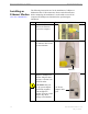
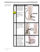


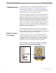
Table Of Contents
- Introduction
- Package Inventory
- Ripwave Models
- Minimum Computing Requirements
- Physical Characteristics
- Installing an Ethernet Modem
- Installing a USB Modem
- Accessing the Internet
- Troubleshooting
- Installing Ripwave Monitor
- TroubleshootingUsing Ripwave Monitor
- Uninstalling Ripwave Monitor
- Installing Navini Diagnostics (NavDiag)
- TroubleshootingUsing Navini Diagnostics (NavDiag)
- Uninstalling Navini Diagnostics
- Installing & Charging the Battery
- Care & Maintenance
- Upgrading the Modem
- ADDENDUM 1: Ripwave™ Modem - PC Troubleshooting
- ADDENDUM 2: End User Software License Agreement

Ripwave Modem User Guide Navini Networks, Inc.
Installing a USB Modem,
continued
Step Action Illustration (using LED Modem)
4. Rotate the antenna on
the Ripwave Modem
180 degrees to the UP
position. This reveals
the Modem’s indicator
lights.
CAUTION! Rotation of
the antenna in any other
direction may cause
damage to the Modem.
5. Turn the Modem ON.
On the 2.4 GHz modem,
do this by flipping the
On/Off switch to the up
position. On all other
models, push the On/Off
button in.
6. If the green Power LED
lights, proceed to Step 7.
(On an LCD Modem,
the display turns on.) If
not, there is a problem
with the Modem or the
AC Power Adapter.
Check all cables for
proper connection. If
there is still a problem,
contact the supplier who
gave you the package.
Signal Strength
Indicator (SSI)
Power
Indicator
Battery
Indicator
Antenna
Signal Strength
Indicator (SSI)
Power
Indicator
Battery
Indicator
Antenna
On/Off
Switc
h
2.4 GHz
2.3, 2.5, 2.6
& 3.5 GHz
Power
Indicator
Power
Indicator
16 Part #40-00097-00 Rev F v1.0
May 21, 2004