
User's Guide

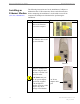
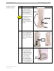


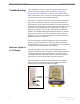
Table Of Contents
- Introduction
- Package Inventory
- Ripwave Models
- Minimum Computing Requirements
- Physical Characteristics
- Installing an Ethernet Modem
- Installing a USB Modem
- Accessing the Internet
- Troubleshooting
- Installing Ripwave Monitor
- TroubleshootingUsing Ripwave Monitor
- Uninstalling Ripwave Monitor
- Installing Navini Diagnostics (NavDiag)
- TroubleshootingUsing Navini Diagnostics (NavDiag)
- Uninstalling Navini Diagnostics
- Installing & Charging the Battery
- Care & Maintenance
- Upgrading the Modem
- ADDENDUM 1: Ripwave™ Modem - PC Troubleshooting
- ADDENDUM 2: End User Software License Agreement
Ripwave Modem User Guide Navini Networks, Inc.
Troubleshooting
Indicator Lights or
LCD Display
After installation, if you are experiencing difficulties with your
Internet connection, please review the
Minimum Computing
Requirements
and Addendum 1 to ensure your computer meets
those requirements. Next, go back over the installation procedures
and ensure those steps were completed properly.
Assuming the computer requirements are met and the installation
steps were completed as required, you will need to observe the
light indicators on the front of the Modem. You also may need to
install the monitoring software. This software is provided on a CD
that came in your Modem package. Navini offers two types of
monitoring software. The first type, called the Navini Ripwave
Monitor, is available with Ripwave Modems that have a software
release
prior to release 4.0. The second type, called the Navini
Diagnostics Tool, is available with Ripwave Modems that have a
software release of 4.0 or greater.
The Navini Monitor and Navini Diagnostics software assists in
solving connection problems as well as providing information
about the battery power in cases where batteries are used. Batteries
are optional with some Ripwave LED Modems.
The indicator lights on the front of the LED Modem provide
valuable information about its operation. They change appearance
to designate the state of the items that they represent. Used in
conjunction with the monitoring software, you can troubleshoot
signal issues, network connections, and power problems.
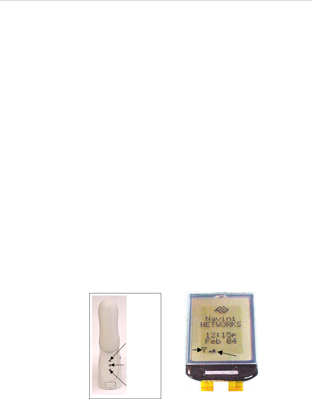
The LCD Display performs the same function as the indicator
lights. However, instead of using colored lights, it provides a
written message and symbols within the display.
Signal Strength
Indicator (SSI)
Power
Indicator
Battery
Indicator
Signal Strength
Indicator (SSI)
Power
Indicator
Battery
Indicator
Power
Indicator
Battery
Indicator
Sync Indicator
Signal Strength Bars
20 Part #40-00097-00 Rev F v1.0
May 21, 2004