
Installation Manual Part 2
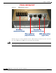
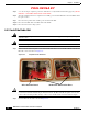
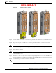
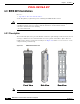
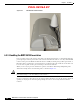
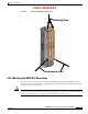
Table Of Contents

PRELIMINARY
6-3
BWX 8415 Basestation Installation and Commissioning Guide
OL-19519-01
Chapter 6 Installation
6.2.2 BWX 8415 Basestation Radio Unit Field Testing
6.2.2 BWX 8415 Basestation Radio Unit Field Testing
THIS SECTION WAS WRITTEN/DEVELOPED, BASED ON THE FIELD TEST KIT LIST OF
MATERIALS AND VERBAL DESCRIPTIONS OF HOW THE FIELD TEST KIT IS INTENDED
TO BE USED. ONCE THE FIELD TEST KIT IS DEVELOPED, THIS SECTION WILL BE
UPDATED TO REFLECT THE ACTUAL EQUIPMENT.
It is recommended that the RU be tested, to ensure that the unit is functioning properly, prior to
installation into the AU. Perform the following steps to connect the RU to the Field Test kit and test the
RU.
Step 1 Connect the RU to the Fan/Cal Board assembly. Refer to Figure 6-2.
- Connect the RU to the fans/cooling system
- Connect the RU to the Cal board (using the 9 RF cables included in the Field Test kit)
- Connect the GPS antenna to the GPS Antenna port on the bottom of the RU.
Figure 6-2 RU to Fan/Cal Board Assembly Connection
Step 2 Connect a ground cable to the RU ground. Tighten the nuts to 48 in. lbs. (5.4 Nm). Refer to Figure 6-3.
Step 3 Connect the DC power cable leads (2 RTN and 2 -48V) to the RU. Tighten the nuts to 48 in. lbs.
(5.4 Nm). Refer to Figure 6-3.
Figure 6-3 Ground Cable and DC Power Cable Connections
Step 4 Connect an RJ-45-to-DB-9 serial cable to the Console port on the RU and to the Field Technician’s
laptop PC.
- Using a terminal application (such as TeraTerm or Hyperterminal), set the following port
parameters:
Baud Rate: 9600
Data: 8 bit
Parity: None
Stop: 1 bit
Flow Control: None
Step 5 Power up the RU by connecting the DC power cable to a DC power source (48V power supply).
Note Once the RU is powered up, it will begin to boot. The boot process can be monitored from the terminal
application on the laptop PC.
Step 6 Modify the bootline parameters as necessary. (MORE DETAILS ONCE FIELD TEST KIT IS
AVAILABLE)